TM-9-2330-202-13-P - Page 283 of 552
WHEEL BEARING ADJUSTMENT
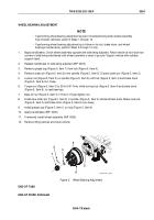
1.
Install wheel assembly (WP
0034) but leave support stand under axle.
2.
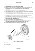
Remove six cap screws (Figure 7, Item 1), lockwashers (Figure 7, Item 2), access cover (Figure 7, Item 3),
and paper gasket (Figure 7, Item 4). Discard lockwashers (Figure 7, Item 2) and paper gasket
(Figure 7, Item 4).
3.
Remove outer bearing sleeve nut (Figure 7, Item 9) and key washer (Figure 7, Item 8).
4.
Loosen adjusting nut (Figure 7, Item 5). Turn wheel assembly (Figure 7, Item 6) until wheel assembly binds.
Loosen adjusting nut 1/6 turn or until wheel assembly does not bind.
5.
Try to move wheel assembly (Figure 7, Item 6) by rocking. Wheel assembly should not move. If it does move,
repeat Step 4.
6.
Mate key washer (Figure 7, Item 8) and spindle. Slide key washer against adjusting nut (Figure 7, Item 5).
Dowel pin (Figure 7, Item 7) should enter one of the holes in key washer (Figure 7, Item 8). If dowel pin
(Figure 7, Item 7) does not enter hole in key washer (Figure 7, Item 8), perform Step 7.
7.
Remove key washer (Figure 7, Item 8). Turn it over and reinstall. If dowel pin (Figure 7, Item 7) does not enter
hole in key washer (Figure 7, Item 8), perform Step 8.
8.
Loosen adjusting nut (Figure 7, Item 5) and repeat Steps 4 through 7.
9.
Install outer bearing sleeve nut (Figure 7, Item 9), new paper gasket (Figure 7, Item 4), access cover
(Figure 7, Item 3), six new lockwashers (Figure 7, Item 2), and cap screws (Figure 7, Item 1).
10.
Raise trailer with lifting device and remove support stand. Lower trailer to ground.
1
2
3
4
5
6
7
8
9
M116_M101_4-90_5
Figure 7.
Wheel Bearing Adjustment.
END OF TASK
END OF WORK PACKAGE
TM 9-2330-202-13&P
0055
0055-7/8 blank
Back to Top

