TM-9-2330-202-13-P - Page 282 of 552
ASSEMBLY - Continued
7.
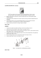
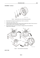
Pack inner bearing hub cone and roller (Figure 5, Item 3) with grease and install.
8.
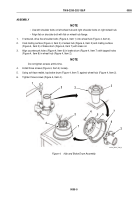
Install new seal (Figure 5, Item 2) and retaining ring (Figure 5, Item 1).
1
2
3
M116_M101_4-90_4A
Figure 5.
Retaining Ring, Seal, and Inner Bearing Assembly.
END OF TASK
INSTALLATION
1.
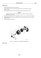
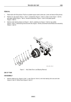
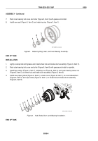
Lightly coat spindle with grease and install wheel hub and brake drum assembly (Figure 6, Item 9).
2.
Pack outer bearing hub cone and roller (Figure 6, Item 8) with grease and install on spindle.
3.
Install key washer (Figure 6, Item 7), adjusting nut (Figure 6, Item 6), and outer bearing sleeve nut
(Figure 6, Item 5) on wheel hub and brake drum assembly (Figure 6, Item 9).
4.
Install new paper gasket (Figure 6, Item 4), access cover (Figure 6, Item 3), six new lockwashers
(Figure 6, Item 2), and cap screws (Figure 6, Item 1) on wheel hub and brake drum assembly
(Figure 6, Item 9).
1
2
3
4
5
6
7
8
9
M116_M101_4-90_4B
Figure 6.
Hub, Brake Drum, and Bearing Installation.
END OF TASK
TM 9-2330-202-13&P
0055
0055-6
Back to Top

