TM-9-2330-247-14-P - Page 71 of 320
TM 9-2330-247-14&P
Section VI. ELECTRICAL SYSTEM MAINTENANCE
Page
Page
Blackout Stoplight Assembly . . . . . . . . . . .
4-22
lntervehicular Cable . . . . . . . . . . . . . . . . . .
4-35
Chassis Wiring Harness . . . . . . . . . . . .
4-25
Service Stoplight-Taillight Assembly . . . . .
4-19
Composite Light Assembly . . . . . . . .
4-17
Wiring Diagrams . . . . . . . . . . . . . . . . . . . . .
4-38
4-23.
COMPOSITE LIGHT ASSEMBLY
This Task Covers:
a.
Removal
c.
Installation
b. Lamp, Lens, and Door Assembly Replacement
Initial Setup:
Equipment Conditions:
Tools/Test Equipment:
l Intevehicular cable disconnected from towing ve-
l Handle, ratchet, 3/8 in. drive
hicle (para 2-12).
l Screwdriver, flat-tip, 1/4 in.
l Socket, 3/8 in. drive, 9/16 in.
ACTION
LOCATION
ITEM
REMARKS
NOTE
l
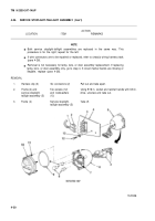
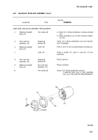
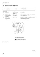
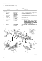
Both composite light assemblies are replaced in the same way. Lamps, lens, and
door assemblies are also replaced in the same way. This procedure is for the left;
repeat for the right.
l If wire connectors are to be repaired or replaced, refer to chassis wiring harness task
(para 4-26).
. Removal is not necessary for lamp, lens, or door assembly replacement. If replacing
lamp, lens, or door assembly only, go to step 4. If circuit marker bands are missing or
illegible, replace (para 4-26).
4-17
Back to Top

