TM-9-2330-334-13-P - Page 422 of 1184
TM 9-2330-334-13&P
CIRCUIT BREAKER, MODULE,
0057 00
AND CONNECTOR REPLACEMENT - Continued
Change 1
0057 00-4
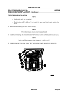
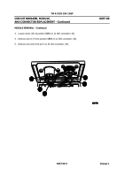
MODULE REMOVAL
NOTE
•
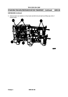
This task shows locations of Voltage converter box module wiring connection
points.
Modules 1 through 5 are removed the same way, Module 3 is shown. Refer
to
Table 1.
Voltage Converter Box Module Wiring Connections for details.
•
Tag wires and connection points prior to disconnecting.
•
Remove plastic cable ties and convoluted tubing as required.
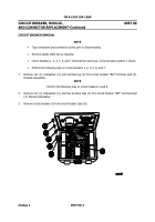
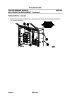
1.
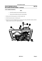
Remove nut (7), lockwasher (8), and wire (9) from circuit breaker CB7 “BAT” terminal stud
(10). Discard lockwasher.
2.
Remove nut (11), lockwasher (12), and wire (13) from right ground stud (14). Discard
lockwasher.
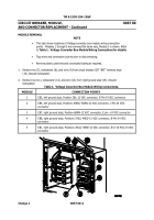
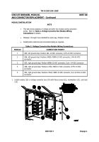
Table 1.
Voltage Converter Box Module Wiring Connections.
MODULE
CONNECTION POINTS
1
CB3, left ground stud, Position 2BL-12 VDC connector, E-Pin-24 VDC connector
2
CB4, left ground stud, Positions 4RED/ 5GRN-12 VDC connector, J-Pin-24 VDC
connector
3
CB7, right ground stud, Position 6BRN-12 VDC connector, E pin –24 VDC connector
4
CB8, right ground stud, Positions 3YEL/ 4RED-12 VDC connector, B-Pin-24 VDC
connector
5
CB1, right ground stud, Positions 7BLU/ 4RED-12 VDC connector, B-/J-/K-Pins-24 VDC
connector
Back to Top

