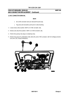
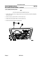
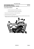
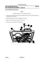
TM-9-2330-334-13-P - Page 425 of 1184
TM 9-2330-334-13&P
CIRCUIT BREAKER, MODULE,
0057 00
AND CONNECTOR REPLACEMENT - Continued
0057 00-7
Change 1
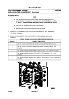
MODULE INSTALLATION
NOTE
•
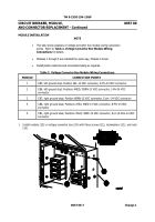
This task shows locations of voltage converter box module wiring connection
points.
Refer to
Table 2. Voltage Converter Box Module Wiring
Connections
for details.
•
Modules 1 through 5 are installed the same way, Module 3 shown.
•
Install plastic cable ties and convoluted tubing as required.
Table 2.
Voltage Converter Box Module Wiring Connections.
MODULE
CONNECTION POINTS
1
CB3, left ground stud, Position 2BL-12 VDC connector, E-Pin-24 VDC connector
2
CB4, left ground stud, Positions 4RED/ 5GRN-12 VDC connector, J-Pin-24 VDC
connector
3
CB7, right ground stud, Position 6BRN-12 VDC connector, E pin –24 VDC connector
4
CB8, right ground stud, Positions 3YEL/ 4RED-12 VDC connector, B-Pin-24 VDC
connector
5
CB1, right ground stud, Positions 7BLU/ 4RED-12 VDC connector, B-/J-/K-Pins-24 VDC
connector
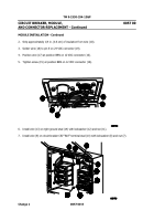
1.
Install module (23) in voltage converter box (24) with three screws (22), lockwashers (21), and nuts
(20).
Back to Top

