TM-9-2330-342-23-P - Page 471 of 1348
INSTALLATION
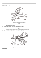
NOTE
Ensure male and female ends of connectors are securely latched together.
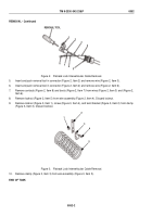
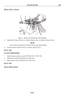
1.
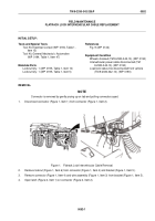
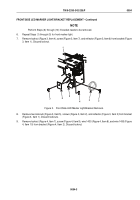
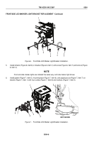
Connect connector (Figure 4, Item 1) to connector (Figure 4, Item 2).
1
2
2
Figure 4.
Flatrack Lock Sensor Installation.
NOTE
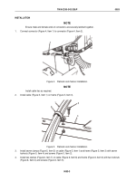
Install cable ties as required.
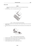
2.
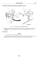
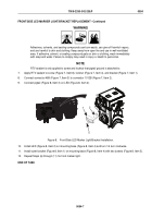
Install cable (Figure 5, Item 1) on frame (Figure 5, Item 3).
1
5
2
3
4
Figure 5.
Flatrack Lock Sensor Installation.
3.
Install seven clamps (Figure 5, Item 5) on cable (Figure 5, Item 1) and frame (Figure 5, Item 3) with seven
locknuts (Figure 5, Item 4) and screws (Figure 5, Item 2).
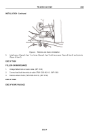
4.
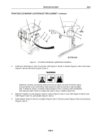
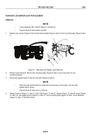
Install two clamps (Figure 6, Item 7) on cable (Figure 6, Item 6) and frame (Figure 6, Item 3) with two locknuts
(Figure 6, Item 4) and screws (Figure 6, Item 5).
TM 9-2330-342-23&P
0053
0053-3
Back to Top

