TM-9-2330-342-23-P - Page 663 of 1348
CLEANING/INSPECTION - Continued
11.
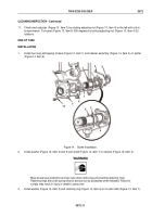
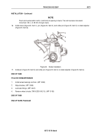
Check slack adjuster (Figure 13, Item 3) by rotating adjusting nut (Figure 13, Item 4) to the left with a lb-in
torque wrench. Turn gear (Figure 13, Item 5) 360 degrees by turning adjusting nut (Figure 13, Item 4) 22
rotations.
END OF TASK
INSTALLATION
1.
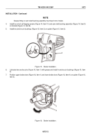
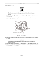
Install four long self tapping screws (Figure 14, Item 1) and retainer assembly (Figure 14, Item 4) on spider
(Figure 14, Item 2).
10
9
8
7
6
5
1
2
3
4
Figure 14.
Brake Installation.
2.
Install washer (Figure 14, Item 3) and S-cam shaft (Figure 14, Item 7) in retainer (Figure 14, Item 4).
WARNING
Wear proper eye protection and use care when removing and installing retaining rings.
Retaining rings are under spring tension and can act as projectiles when released. Failure to
comply may result in injury or death to personnel.
3.
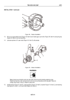
Install washer (Figure 14, Item 5) and retaining ring (Figure 14, Item 6) on S-cam shaft (Figure 14, Item 7).
TM 9-2330-342-23&P
0072
0072-11
Back to Top

