TM-9-2330-342-23-P - Page 815 of 1348
ASSEMBLY - Continued
23.
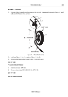
Using an inflation hose with an in-line gauge and clip-on chuck, inflate wheel/tire assembly (Figure 14, Item 3)
to 87 psi (600 kPa) and check for leaks.
SAFETY CAGE
TRAJECTORY
INFLATION HOSE
3
2
1
Figure 14.
Wheel/Tire Assembly.
24.
Install cap (Figure 14, Item 1) on adapter (Figure 14, Item 2).
25.
Remove wheel/tire assembly (Figure 14, Item 1) from safety guard.
END OF TASK
FOLLOW-ON MAINTENANCE
1.
Install tire on trailer. (WP
0094)
2.
Remove wheel chocks (TM 9-2330-342-10). (WP
0190)
END OF TASK
END OF WORK PACKAGE
TM 9-2330-342-23&P
0093
0093-15/16 blank
Back to Top

