TM-9-2330-342-23-P - Page 824 of 1348
REMOVAL - Continued
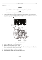
HYDRAULIC
FLOOR JACK
WHEEL CHOCK
1
2
3
4
5
7
9
8
6
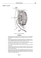
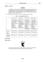
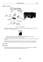
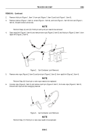
Figure 1.
Bumper Removal.
2.
Remove eight locknuts (Figure 1, Item 5) and screws (Figure 1, Item 7) from bumper (Figure 1, Item 1) and
frame (Figure 1, Item 6). Discard locknuts.
WARNING
Keep a firm grip on bumper as bumper is being moved to keep bumper from rolling forward.
Failure to comply may result in injury or death to personnel.
3.
With the aid of an assistant and hydraulic floor jack, lower bumper (Figure 1, Item 1) away from frame (Figure
1, Item 6).
4.
Remove two nuts (Figure 1, Item 4), lockwashers (Figure 1, Item 3), washers (Figure 1, Item 2), washers
(Figure 1, Item 8), and screws (Figure 1, Item 9) from bumper (Figure 1, Item 1). Discard lockwashers.
END OF TASK
INSTALLATION
1.
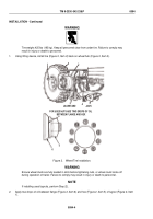
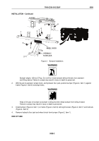
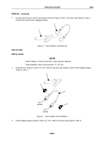
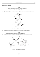
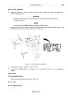
Install two washers (Figure 2, Item 8), screws (Figure 2, Item 9), washers (Figure 2, Item 2), lockwashers
(Figure 2, Item 3), and nuts (Figure 2, Item 4) on bumper (Figure 2, Item 1).
TM 9-2330-342-23&P
0095
0095-2
Back to Top

