TM-9-2330-356-14
SEMITRAILER, TANK: 5000 GALLON, BULK HAUL, SELF LOAD/UNLOAD M967 AND M967A1; SEMITRAILER, TANK: 5000 GALLON, FUEL DISPENSING, AUTOMOTIVE M969 AND M969A1; SEMITRAILER, TANK: 5000 GALLON, FUEL DISPENSING, UNDER/OVERWING AIRCRAFT M970 AND M970A1
TECHNICAL MANUAL; OPERATOR’S, UNIT, DIRECT SUPPORT, AND GENERAL SUPPORT MAINTENANCE MANUAL
OCTOBER 1990
TM-9-2330-356-14 - Page 445 of 528
TM 9-2330-356-14
(i)
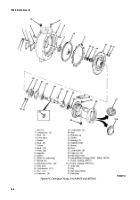
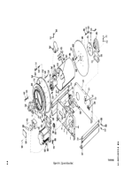
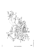
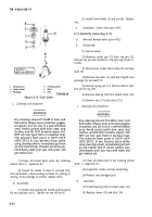
Install original number of thrust washers
(25) over spacer (28).
(j)
Install collar (24) onto disc (20) using six
capscrews (21), lockwashers (22), and nuts (23).
(k)
Install disc (24)) over axle shaft (34), and
attach disc to four spacers (28) with four studs (18),
lockwashers (74), and nuts (73). Tighten set screw (19).
(l)
Install bearing and collar (17) onto axle
shaft (34). Lock onto
shaft by rotating coIIar
counterclockwise. Tighten set screw.
(m)
Attach a suitable hoist to the drum (26)
and raise drum into position over frame. install spacer (16)
between bearing and collar (17), and frame (15). Install
two capscrews (11), flatwashers (12), lockwashers (13), and
nuts (14). Next, install two capscrews (7), flatwashers (8),
lockwashers (9), and nuts (10).
(n)
Position pinion guard (4) and pinion
bearing assembly (5) onto frame (6), and secure to frame
with two capscrews (l), lockwashers (2), and flatwashers
(3). Be sure pinion-on-pinion bearing assembly (5) mates
properly with bevel gear (51).
e.
Installation.
Install hose reel (para 5-24).
Section IV. METERS
8-7.
Meter (M970 and M970A1)
b.
Meter Head Seal Replacement.
a.
General.
The meters on the M969, M969A1,
M970, and M970A1
semitrailers
are not to be repaired
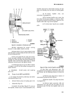
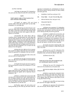
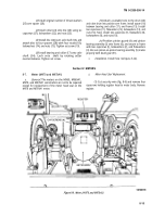
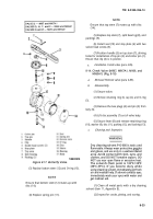
(1) Cut security wire (fig. 8-9) and remove four
except for replacement of the meter head seal on the
capscrews holding register head to meter body. Remove
M970 and M970A1 meter.
register.
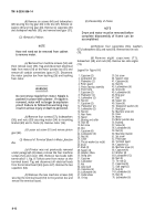
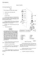
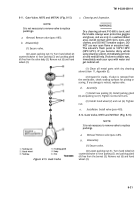
Figure
8-9.
Meter (A1970 and M970A1).
8-15
Back to Top

