TM-9-2330-356-14
SEMITRAILER, TANK: 5000 GALLON, BULK HAUL, SELF LOAD/UNLOAD M967 AND M967A1; SEMITRAILER, TANK: 5000 GALLON, FUEL DISPENSING, AUTOMOTIVE M969 AND M969A1; SEMITRAILER, TANK: 5000 GALLON, FUEL DISPENSING, UNDER/OVERWING AIRCRAFT M970 AND M970A1
TECHNICAL MANUAL; OPERATOR’S, UNIT, DIRECT SUPPORT, AND GENERAL SUPPORT MAINTENANCE MANUAL
OCTOBER 1990
TM-9-2330-356-14 - Page 441 of 528
TM 9-2330-356-14
(4)
Drum Assembly.
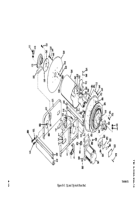
capscrews (1), lockwashers (2), and flatwashers (3). Ensure
that pinion-on-pinion bearing assembly (5) mates properly
(a)
Using six capscrews (51), lockwashers
with bevel gear (30).
(52), and nuts (53), fasten the collar (47) to the disc (46).
e.
Installation.
Install hose reel (para 5-23).
NOTE
8-6.
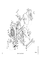
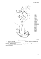
Hose Reel - 1¼ and 1½-inch (Fig. 8-8)
Install original number of thrust washers that
were removed at disassembly.
a.
Removal.
Remove hose reel (para 5-24).
(b)
Install six spacers (24) and thrust
b.
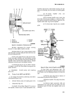
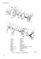
Disassembly (Fig.
8-8).
washers (50) ‘to disc (46). Secure with ‘six nuts (78),
lockwashers (77), and studs (49).
(1)
Drum Assembly.
(c)
Install bearing and collar (45) onto rude
(a)
Remove two capscrews (1), lockwashers
shaft (35). Rotate collar counterclockwise to lock bearing
(2), and flatwashers (3) securing the pinion bearing
and collar on axle shaft. Install axle shaft through collar
assembly (hose reel lock) (5) to the frame (6). Remove the
(47) until bearing and collar (45) is against collar (47).
pinion bearing assembly (5) and the guard (4).
Tighten set screw (44).
(b)
Attach a suitable hoist to drum (26), and
(d)
Assemble the outlet elbow (38) by
remove the two capscrews (7), flatwashers (8),
installing a new O-ring (43) between the outlet elbow (38)
lockwashers (9), and nuts (10). Then remove two
and the outlet adapter (42). Use four capscrews (40) and
capscrews (11), flatwashers (12), lockwashers (13), and
lockwashers (41) to secure the outlet elbow (38) and outlet
nuts (14). Lift drum assembly from front and rear frame (6
adapter together. Assemble the outlet elbow (38) to the
and 15) and place on a suitable work bench. Be sure to
adapter elbow (34) by installing a new O-ring (39) between
keep the two spacers (16) with the drum assembly.
the outlet elbow (38) and the adapter elbow (34). Use four
capscrews (36) and lockwashers (37) to secure the two
(c) Loosen set screw on bearing collar. Use
elbows (34 and 38) together.
punch to rotate collar clockwise to release bearing and
collar from shaft.
(e)
Install the drum (48) over the six spacers
(24). Install the adapter elbow (34) onto axle shaft (35).
(d)
Remove four nuts (73), lockwashers (74),
Install the capscrew (31), lockwasher (32), and nut (33).
and studs (18) from disc (20). Remove six capserews (21),
lockwashers (22), and nuts (23). Remove collar (24).
(f)
Position the bevel gear (30) on disc (22)
and secure with six capscrews (29).
(g) Position the ring gear (27) and six spacers
(28) on the disc (22), and secure with six screws (25) and
lockwashers (26).
(e) Remove drum (26).
NOTE
Take note of how many thrust washers (25)
are used between spacers and disc.
(h)
Install the disc (22) onto the six spacers
(24) by securing with six studs (23), lockwashers (77), and
(f)
Remove four nuts (75), lockwashers (76),
nuts (78).
studs (27), thrust washers (25), and spacers (28).
(i)
Put a new O-ring (21) between the
adapter elbow (34) and the swivel joint (20), and fasten the
elbow and swivel joint together with six capscrews (18) and
lockwashers (19).
(j)
Attach a suitable hoist to the drum (48)
and raise drum to position over frame. Install spacers (16
and 17) between bearing and collar (45) and frame (15).
Install two capscrews (7), flat washers (8), lockwashers (9),
and nuts (10). Next, install two capscrews (11), flat washers
(12), lockwashers (13), and nuts (14).
(k)
Position spacer (4) and pinion and
bearing assembly (5) onto frame (6), and secure with two
(g) Unscrew adapter elbow (29) from the
swing joint (30).
(h)
Remove capscrew (31), lockwasher (32),
and nut (33). Remove axle shaft (34). Remove four
capscrews (35) and lockwashers (36) securing outlet elbow
(37) to adapter elbow (29). Remove outlet elbow (37) and
O-ring (38). Discard O-ring.
(i)
Loosen set screw (39) and remove swing
joint (30) from the support collar (40).
(j)
Remove six capscrews (41), lockwashers
(43), and nuts (42). Remove support collar (40).
8-11
Back to Top

