TM-9-2330-356-14
SEMITRAILER, TANK: 5000 GALLON, BULK HAUL, SELF LOAD/UNLOAD M967 AND M967A1; SEMITRAILER, TANK: 5000 GALLON, FUEL DISPENSING, AUTOMOTIVE M969 AND M969A1; SEMITRAILER, TANK: 5000 GALLON, FUEL DISPENSING, UNDER/OVERWING AIRCRAFT M970 AND M970A1
TECHNICAL MANUAL; OPERATOR’S, UNIT, DIRECT SUPPORT, AND GENERAL SUPPORT MAINTENANCE MANUAL
OCTOBER 1990
TM-9-2330-356-14 - Page 433 of 528
TM 9-2330-356-14
WARNING
(b) Then remove enough shims to move the
impeller away from the wear plate a distance of 0.015-inch.
Be careful when removing the Impeller from
(c)
Rotate the pump by hand to make sure
the pump. The spring load on the mechanical
the impeller is not binding or scraping.
seal may cause the impeller to fly off the shaft
as it is being removed, causing serious injury
(d)
Minor nicks on edges of impeller vanes
to personnnel.
can be removed by finishing with a fine stone.
(c)
Apply force to strap wrench in a
(e)
If the impeller and wear plates are worn
count counterclockwise direction. Using a block of hard wood
excessively, they must be replaced.
and a hammer, hit the hub of impeller to loosen it on the
(f)
After replacement of the impeller, wear
shaft. Remove the impeller by unscrewing it from the
plate, or impeller shaft, check for clearance between the
impeller shaft.
BACK of the impeller and the seal plate. If the impeller
(4) Pull the seal plate (15) and the mechanical
scrapes when the seal plate (15) is installed, add another
seal (16) from the impeller shaft.
gasket (19) of sufficient thickness between the seal plate
and the pump casing.
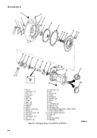
(5) Remove four capscrews (12) and lockwashers
(13) from bearing cap (11). Remove the bearing cap and
discard gasket (10).
(6) Remove pump coupling (28) and key (29)
from opposite end of shaft, if these items were not already
removed.
(7) Using a soft hammer, hit the keyed end of the
impeller shaft to remove the shaft (8), bearings (9 and 6),
and spacer (7) from intermediate housing (3).
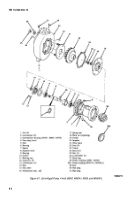
(8) Remove seal (5) from intermediate housing.
Discard the seal.
(9) Remove the seal (14) from the bearing cap
(11). Discard the seal.
(2)
Mechanical Seal (16).
Inspect the mating
surfaces of the seal for wear, scoring, grooves or other
damage which can cause leakage. If any of the seal parts
are worn, replace the entire seal. Never mix old and new
parts of a seal.
(3) Impeller Shaft (8).
Inspect the impeller shaft
for nicks, scratches, scoring or other damage. Replace the
shaft if damaged.
(4)
Bearings (6 and 9).
Rotate bearings by hand
and check for binding or wear. Replace bearings if wear is
found. The bearings are a light press fit on the impeller
shaft and a snug push fit in the housing. If the shaft is worn
so the bearing slips on and off easily, the shaft must be
replaced. Replace the housing if the bearings do not fit
snugly into the bearing bore.
(10) Remove snap ring (27), bearing (9), and
(5)
Gaskets and Seals.
Whenever a pump is
bearing (6) from impeller shaft (8).
overhauled, ail gaskets should be replaced. However, if
old gaskets must be reused, soak the gaskets in water to
(11) The wear plate (21) is fastened to the volute
prevent them from drying out and shrinking. Inspect all
with two nuts (25) and lockwashers (26). Remove the wear
seals carefully and replace any that are damaged.
plate only if excessive wear is evident and replacement is
necessary (step e).
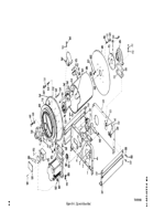
Assembly (Fig 8-1).
d.
C[eaning.
Refer to paragraph 5-8.
(1) Install new seal (5) in bore of intermediate
housing. Lip of seal must be toward the impeller.
e.
Inspection and Repair (Fig. 8-1).
NOTE
(1) Impeller and Wear Plate. The
open impeller
(20) uses a wear plate (21) in front of the impeller vanes to
minimize internal pump leakage. This wear plate normally
receives most of the wear. Pump efficiency will decrease
considerably when the clearance between the wear plate
and impeller exceeds 0.035-inch. Normally, shims (18) can
be added to bring clearance within limits.
(a)
Add shims until rubbing just starts to
occur when the impeller and wear plate are secured in
place.
Loading groove in bearings must be installed
toward the shoulder or center (largest
diameter) of the impeller shaft.
(2) Press bearing (9) over threaded end of
impeller shaft (8) and install snap ring (27).
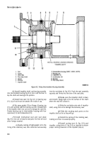
(3) Put spacer (7) onto impeller shaft against
bearing just installed. Press bearing (6) with loading
groove towards spacer onto keyed end of impeller shaft
(fig. 8-2).
8-3
Back to Top

