TM-9-2330-356-14
SEMITRAILER, TANK: 5000 GALLON, BULK HAUL, SELF LOAD/UNLOAD M967 AND M967A1; SEMITRAILER, TANK: 5000 GALLON, FUEL DISPENSING, AUTOMOTIVE M969 AND M969A1; SEMITRAILER, TANK: 5000 GALLON, FUEL DISPENSING, UNDER/OVERWING AIRCRAFT M970 AND M970A1
TECHNICAL MANUAL; OPERATOR’S, UNIT, DIRECT SUPPORT, AND GENERAL SUPPORT MAINTENANCE MANUAL
OCTOBER 1990
TM-9-2330-356-14 - Page 438 of 528
TM 9-2330-356-14
(k)
Remove six capscrews (51), lockwashers
(52), and nuts (53) securing the collar (47) to the disc (46).
Remove the collar.
(2)
Removal of Motor.
NOTE
Hose reel need not be removed from cabinet
to remove motor.
(a)
Remove four machine screws (54).
Remove cover (55). Tag and disconnect electrical leads
from motor (56) at the motor junction box (57), and
remove all conduit connections (para 4-27). Disconnect
the motor junction box from bushing (58) and bushing
from motor.
WARNING
DO NOT remove nipple from motor. Nipple is
packed in place with plaster. If nipple Is
removed, motor will no longer be explosion
proof. Failure to follow this warning may
result in serious injury or death to personnel.
(b)
Remove four screws (59), lockwashers
.(60), and nuts (61) securing motor (56) to mounting
bracket (62) and to frame (6). Remove motor (56).
(c)
Remove two screws (59), lockwashers
(60), and nuts (61). Remove mounting bracket (62).
(d)
Loosen set screw (63) and remove pinion
gear (64).
(3)
Removal of Terminal Board in Motor Junction
Box.
(a) If
motor was not previously removed
under paragraph (2) above, remove the four machine
screws (54) and cover (55). Remove two leads with
terminals (11, fig. 8-7) that come from motor at the
terminal board. Tag and disconnect all electrical leads
from the terminal board (65) (para 4-27). Remove the two
capacitors (66).
(b)
Remove the two machine screws (67)
securing the terminal board (65) to the junction box and
remove the terminal board.
(4)
Disassembly of Frame.
NOTE
Drum and motor must be removed before
complete disassembly of frame can be
accomplished.
(a)
Remove four capscrews (68), washers
(69), lockwashers (70), and nuts (71). Remove two tie rods
(72).
(b)
Remove eight capscrews (73), lock-
washers (70), and nuts (71). Remove two side angles (74).
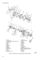
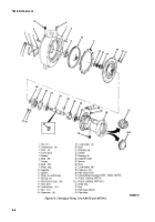
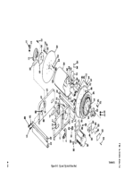
Legend for figure 8-6:
1. Capscrew (2)
2. Lockwasher (2)
3. Flatwasher (2)
4. Spacer
5. Pinion bearing assembly
6. Front frame
7. Capscrew (2)
8. Flatwasher (2)
9. Lockwasher (2)
10. Nut (2)
11. Capscrew (2)
12. Flatwasher (2)
13. Lockwasher (2)
14. Nut (2)
15. Rear frame
16, Spacer
17. Spacer
18. Capscrew (6)
19. Lockwasher (6)
20. Swivel joint
21. O-ring
22. Disc
23. Stud (6)
24. Spacer (6)
25. Screw (6)
26. Lockwasher (6)
27. Ring gear
28. Spacer (6)
29. Capscrew (6)
30. Bevel gear
31. Capscrew
32. Lockwasher
33. Nut
34. Adapter elbow
35. Axle shaft
36. Capscrew (4)
37. Lockwasher (4)
38. Outlet elbow
39. O-ring
40. Capscrew (4)
41. Lockwasher (4)
42. Outlet adapter
43. O-ring
44. Set screw
45. Bearing and collar
46. Disc
47. Collar
48. Drum
49. Stud (6)
50. Thrust washer (as req’d)
51. Capscrew (6)
52. Lockwasher (6)
53. Nut (6)
54. Machine screw (4)
55. Cover
56. Motor
57. Motor junction box
58. Bushing
59. Screw (6)
60. Lockwasher (6)
61. Nut (6)
62. Mounting bracket
63. Set screw
64. Pinion gear
65. Terminal board
66. Capacitor (2)
67. Machine screw (2)
68. Capscrew (4)
69. Washer (4)
70. Lockwasher (12)
71. Nut (12)
72. Tie rod (2)
73. Capscrew (8)
74, Side angle (2)
75. Pinion guard
76. Nut (6)
77. Lockwasher (6)
78. Nut (6)
8-8
Back to Top

