TM-9-2330-356-14
SEMITRAILER, TANK: 5000 GALLON, BULK HAUL, SELF LOAD/UNLOAD M967 AND M967A1; SEMITRAILER, TANK: 5000 GALLON, FUEL DISPENSING, AUTOMOTIVE M969 AND M969A1; SEMITRAILER, TANK: 5000 GALLON, FUEL DISPENSING, UNDER/OVERWING AIRCRAFT M970 AND M970A1
TECHNICAL MANUAL; OPERATOR’S, UNIT, DIRECT SUPPORT, AND GENERAL SUPPORT MAINTENANCE MANUAL
OCTOBER 1990
TM-9-2330-356-14 - Page 428 of 528
TM 9-2330-356-14
(b)
Inspect all connections to be sure that
they are properly clinched and soldered. Inspect the
insulation for evidences of damage.
(c)
The only way to check for field coil
shorts is to use the starting motor bench test.
(4)
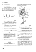
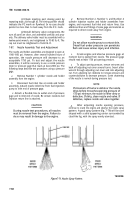
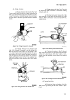
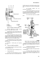
Testing Brush Springs (Fig. 7-86).
Measure
brush spring tension with a tension meter. Push the brush
and take a reading just as the brush projects a little from
the brush holder. On a new brush the spring tension
should be 32-40 ounces. If brush spring tension is below 20
ounces, replace. Spring tension can be changed by twisting
the spring at the holder with long nose pliers.
Figure 7-86. Testing Brush Spring Tension.
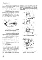
(5)
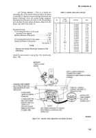
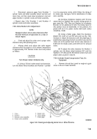
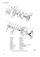
Testing Solenoid Switch (Fig. 7-87).
(a)
Ensure that plunger moves freely in coil.
Measure the pull-in coil current draw by using Test A.
Current should not exceed 16 amps.
(b)
Measure the hold-in draw using Test B.
Current should not exceed 6 amps.
(c)
Total hold and pull current draw using
Test C is 22 amps. Total current draw should not exceed 25
amps.
(d)
Replace a solenoid that does not meet
these test specifications.
c.
Test After Reassembly.
(1) After the motor is assembled, check the
armature end play by inserting thickness gage between
thrust washer (21, fig. 7-62) and pinion housing (22). End
play should be between 0.005-inch and 0.030-inch. Adjust
end play by adding or removing thrust washers (21,
fig. 7-62) on the commutator end of the armature.
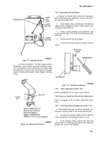
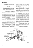
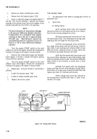
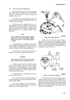
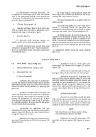
(2) Before installing, check the pinion clearance.
Proper clearance is important to ensure starter engage-
ment. Press on solenoid core to shift the pinion into full
mesh. Measure the clearance between pinion and pinion
stop (fig. 7-87). Clearance should be 0.07 to 0.12-inch. Ad-
just the link screw on the end of the solenoid plunger for
proper clearance.
Figure 7-87. Testing Solenoid Switch.
Figure 7-88. Checking Pinion Clearance.
7-72
Back to Top


