TM-9-2330-356-14
SEMITRAILER, TANK: 5000 GALLON, BULK HAUL, SELF LOAD/UNLOAD M967 AND M967A1; SEMITRAILER, TANK: 5000 GALLON, FUEL DISPENSING, AUTOMOTIVE M969 AND M969A1; SEMITRAILER, TANK: 5000 GALLON, FUEL DISPENSING, UNDER/OVERWING AIRCRAFT M970 AND M970A1
TECHNICAL MANUAL; OPERATOR’S, UNIT, DIRECT SUPPORT, AND GENERAL SUPPORT MAINTENANCE MANUAL
OCTOBER 1990
TM-9-2330-356-14 - Page 420 of 528
TM 9-2330-356-14
7-86. Fuel Injection Pump
indicates that a leak is present. The pressure must remain
above 250 psi for at least 30 seconds.
a.
Test, After Rebuilding.
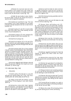
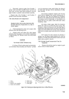
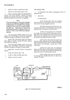
(1) Turn pump upside down and depress tappet
with thumb. Tappet should recede 1/16-inch into face gear
(fig. 7-74). If tappet cannot be depressed 1/16-inch into face
gear, plunger sleeve pin (5, fig. 7-46) is improperly alined.
Disassemble pump and re-aline pin (para 7-69).
Figure 7-74. Checking Plunger Sleeve Alinement.
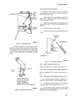
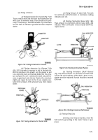
(2)
Remove the overflow valve assembly from
the fuel outlet hole in the pump housing. Install a 1/4-inch
pipe plug (fig. 7-75) into the fuel outlet hole.
(3)
Secure the pump close to a nozzle test stand.
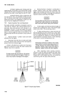
Figure 7-75. Pressure Testing Injection Pump.
(4)
Cap outlet ports (fig. 7-75).
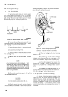
(9) Visual inspection should be as follows:
(5) Install C-clamp on injection pumps to retain
face gear (fig. 7-75).
(a)
Check for leakage by the head locating
screw (13, 7-46).
(6) Aline holes in face gear and housing
(fig. 7-75).
NOTE
A fuel inlet stud can be fabricated with a 1/4-18
NPT pipe die. High pressure tubing must be
used between test stand and the pump
assembly. Always ensure that all external
connections are tight and that the nozzle test
stand is in good order.
(b)
Fuel leakage at the control unit (4)
indicates that either the O-ring (33) is damaged or the
control unit is defective. Replace entire injection pump.
(c) Check for leakage of fuel around the
face gear (28). If leakage is evident, disassemble pump and
inspect O-ring (19). If O-ring is damaged, replace injection
pump.
(d)
Check for fuel leakage between top of
housing and head flange. Disassemble and check O-ring.
If O-ring is damaged, replace injection pump.
(7) Connect the nozzle test stand to the fuel inlet
hole in the pump housing.
b.
On
Equipment Adjustment and Timing.
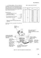
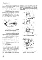
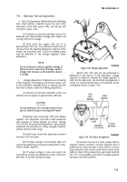
(1)
Timing.
Time the injection pump to the
CAUTION
engine by using the proper thickness timing button
between the pump plunger and tappet (fig. 7-76). Use
Do not exceed a pressure of 400 psi.
method 1 when replacing an old pump if the port closing
dimensions and button number of the old pump were
recorded. Use method 2 if the dimensions are-lost; an old
(8) Slowly operate the nozzle test stand until a
pump is being timed, or when replacing either camshaft or
pressure of 400 psi is achieved. A rapid drop in pressure
crankshaft.
7-64
Back to Top

