TM-9-2330-356-14
SEMITRAILER, TANK: 5000 GALLON, BULK HAUL, SELF LOAD/UNLOAD M967 AND M967A1; SEMITRAILER, TANK: 5000 GALLON, FUEL DISPENSING, AUTOMOTIVE M969 AND M969A1; SEMITRAILER, TANK: 5000 GALLON, FUEL DISPENSING, UNDER/OVERWING AIRCRAFT M970 AND M970A1
TECHNICAL MANUAL; OPERATOR’S, UNIT, DIRECT SUPPORT, AND GENERAL SUPPORT MAINTENANCE MANUAL
OCTOBER 1990
TM-9-2330-356-14 - Page 419 of 528
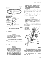
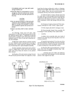
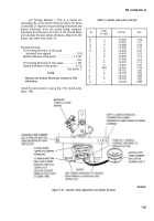
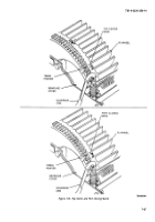
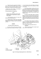
Figure 7-71. Adjusting Shutters.
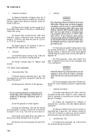
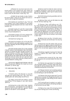
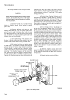
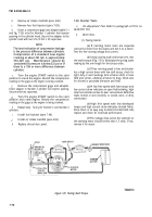
(2) Thermo Unit(Fig.
7-72). With engine at room
temperature, loosen thermo unit guide mounting screws.
The mounting holes in the shutter box are slotted. Slide
the assembly to a position where the thermo unit plunger
rests on roll pins with shutters closed. Tighten mounting
screws.
Figure 7-72. Adjusting Thermo Unit.
TM 9-2330-356-14
7-82. Tachometer Recalibration
a.
Remove six screws which secure the instrument
panel and tilt the panel outward for access to the back of
the tachometer (fig. 4-39).
b.
Start engine. Use a stroboscope and flash on
engine-pump coupling. Increase engine speed until
stroboscope reads 2000 rpm.
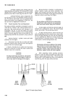
c.
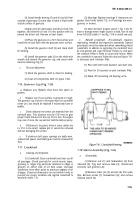
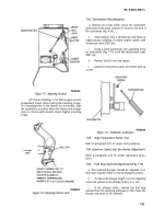
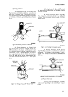
Using a small screwdriver, turn adjusting screw
on tachometer (fig. 7-73) until the tachometer reads
2000 rpm.
d.
Release throttle and stop engine.
e.
Close the instrument panel and
screws.
fasten with six
Figure 7-73. Tachometer Calibration.
7-83.
High Temperature Switch Test
Refer to paragraph 4-23 for proper test procedures.
7-84.
Governor Speed and Sensitivity Adjustment
Refer to paragraph 4-76 for proper adjustment proce-
dures.
7-85.
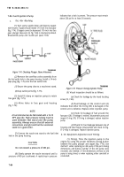
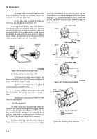
Fuel Stop Solenoid Adjustment (Fig. 7-16)
a.
The solenoid plunger should be adjusted so it
fully stops injection when in the de-energized position.
b.
To adjust the plunger length, turn the adjusting
screw and jamnut on the plunger bottom in or out.
c.
If the plunger sticks, remove the fuel stop
solenoid from its mounting plate (para 7-20). Clean the
plunger and recess in the solenoid.
7-63
Back to Top

