TM-9-2330-356-14
SEMITRAILER, TANK: 5000 GALLON, BULK HAUL, SELF LOAD/UNLOAD M967 AND M967A1; SEMITRAILER, TANK: 5000 GALLON, FUEL DISPENSING, AUTOMOTIVE M969 AND M969A1; SEMITRAILER, TANK: 5000 GALLON, FUEL DISPENSING, UNDER/OVERWING AIRCRAFT M970 AND M970A1
TECHNICAL MANUAL; OPERATOR’S, UNIT, DIRECT SUPPORT, AND GENERAL SUPPORT MAINTENANCE MANUAL
OCTOBER 1990
TM-9-2330-356-14 - Page 422 of 528
TM 9-2330-356-14
(3) Timing
Method 2.
Flow Timing the Pump.
CAUTION
When removing tappets which contain timing
buttons, do not allow the portion of the injec-
tion pump which has the face gear to be lifted
from its position.
(a)
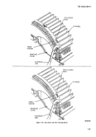
Install a Number 11 or standard timing
button in injection pump. Install pump on engine
(para 7-48).
(b)
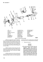
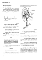
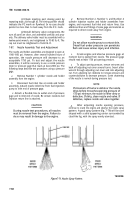
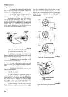
Remove delivery valve cap nut and
delivery valve holder (fig. 7-77). A 12-point socket or box
wrench must be used on delivery valve holder to keep
from damaging this part. Lift out delivery valve spring
only, and leave it out, replacing delivery valve holder and
delivery valve cap nut and gasket.
(c)
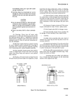
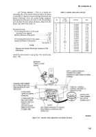
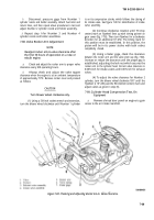
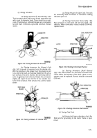
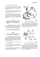
Turn flywheel (fig. 7-78) clockwise until
Number 1 cylinder (closest to blower wheel) is on com-
pression stroke, which follows closing of intake valve.
(d)
Set control unit lever on injection pump
to wide open or up position (compress stop solenoid
plunger spring or remove stop solenoid assembly).
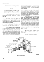
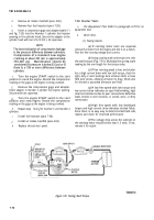
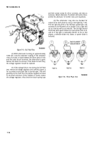
Connect Number 1 cylinder fuel line to Number 1 pump
outlet so that fuel line projects from the engine, hanging
down (fig. 7-15). Position receptacle for fuel under the
line. Connect lines from fuel supply to transfer pumps,
transfer pumps to filter, and filter to injection pump.
Operate fuel transfer pumps to obtain fuel pressure at
injection pump. This can be done on the unit by turning
engine switch to RUN. Rotate flywheel about l-inch
counterclockwise so that P.C. mark (fig. 7-78) is below
timing pointer hole.
(e)
Rotate blower flywheel clockwise until
fuel flows from Number 1 cylinder fuel line. Continue
rotating slowly clockwise until fuel stops flowing. The
point at which fuel stops flowing from Number 1 cylinder
fuel delivery line is the injection pump port closing point.
Stop rotation of engine at exactly the port closing point (1
to 2 drops in 5-10 seconds).
(f)
Check timing pointer in the timing port
on the side of the generator adapter (fig. 7-78). If timing
pointer coincides with the P.C. mark stamped on flywheel,
the injection pump button thickness is correct. If the P.C.
mark on the flywheel is below the pointer, injection pump
is closing early, and will require a thinner button. If the
P.C. mark on flywheel is above the pointer, injection pump
is closing late and will require a t bicker button. Each mark
on flywheel indicates a difference of 0.006-inch button
thickness or two steps in button code number. (Example:
The P.C. mark on flywheel is above pointer. The pointer
indicates 1½ marks difference. A button 0.009-inch
thicker or three steps difference in button number code is
indicated. Since Number 11 button is installed, a letter C
button is needed.)
(g) Remove injection pump and insert
proper timing button, taking the same precautions not to
lift the assembly containing face gear when removing
timing button.
(h)
Repeat injection pump installation.
Figure 7-77. Delivery Valve.
7-66
Back to Top

