TM-9-2330-356-14
SEMITRAILER, TANK: 5000 GALLON, BULK HAUL, SELF LOAD/UNLOAD M967 AND M967A1; SEMITRAILER, TANK: 5000 GALLON, FUEL DISPENSING, AUTOMOTIVE M969 AND M969A1; SEMITRAILER, TANK: 5000 GALLON, FUEL DISPENSING, UNDER/OVERWING AIRCRAFT M970 AND M970A1
TECHNICAL MANUAL; OPERATOR’S, UNIT, DIRECT SUPPORT, AND GENERAL SUPPORT MAINTENANCE MANUAL
OCTOBER 1990
TM-9-2330-356-14 - Page 429 of 528
TM 9-2330-356-14
7-91.
Alternator Test and Adjustments
a.
Test, On Equipment.
Before doing the following
test, check battery condition (para 3-6 and 4-23),
alternator drive belt (para 4-78), and wiring and
connections (para 4-16).
(1) Connect an accurate voltmeter across the
batteries and check battery voltage with engine not
running. Record the voltage.
(2) Now start the engine and run it at
approximately 1000 rpm. The voltmeter should show an
increase from the reading obtained in step (l). If the
voltage rises excessively (over 14.2V), the charging system
may be defective or the voltage regulator needs
adjustment.
NOTE
Do not attempt to adjust regulator voltage if
batteries are in low state of charge. System
voltage will Increase as the batteries receive
a charge.
b.
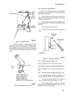
Voltage Adjustment. If
batteries are constantly
undercharging or overcharging, and all other causes, such
as bad connections, damaged wiring, or slipping drive belt
have been checked, make the following adjustment:
(1) Connect an accurate voltmeter across
batteries and run engine at approximately 1000 rpm.
CAUTION
the
Do not attempt to turn the adjustment screw
past its internal stops or damage will result.
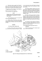
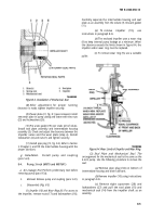
(2) Remove nylon screw (fig. 7-89) from voltage
regulator. Turn adjustment screw with a small screwdriver
and attempt to bring voltage to proper setting
(13.6-14.2V). The ideal setting will be a value which
maintains the batteries in a fully charged condition
without excessive water usage.
(3) Install nylon screw after adjusting to prevent
entrance of dirt and water.
(4) If output voltage is excessively high and
cannot be lowered by turning the adjustment screw,
replace voltage regulator.
(5) If output voltage is low and cannot be
increased by turning the adjustment screw, remove the
alternator for further testing and repair.
Figure 7-89. Voltage Adjustment.
c.
Bench Test.
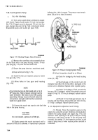
This test can be performed to
determine if the fault is in the alternator, voltage
regulator, or diode trio. Because the voltage regulator is
built into the alternator, the test block arrangement is
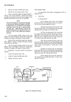
simple. If a commercial test block is not available. use the
arrangement shown in figure 7-90.
Figure
7-90.
Test Block Arrangement.
(1) Connect one end of a short jumper lead to
negative output terminal. Connect opposite end of
jumper lead to a short stiff piece of wire at least 11/2-inches
long. Insert this wire into the small hole in end of brush
holder so that it firmly contacts the outer brush terminal
(fig. 7-91). This procedure overrides the voltage regulator
and gives a full field condition.
7-73
Back to Top

