TM-9-2330-356-14
SEMITRAILER, TANK: 5000 GALLON, BULK HAUL, SELF LOAD/UNLOAD M967 AND M967A1; SEMITRAILER, TANK: 5000 GALLON, FUEL DISPENSING, AUTOMOTIVE M969 AND M969A1; SEMITRAILER, TANK: 5000 GALLON, FUEL DISPENSING, UNDER/OVERWING AIRCRAFT M970 AND M970A1
TECHNICAL MANUAL; OPERATOR’S, UNIT, DIRECT SUPPORT, AND GENERAL SUPPORT MAINTENANCE MANUAL
OCTOBER 1990
TM-9-2330-356-14 - Page 424 of 528
TM 9-2330-356-14
(i)
Check injection port closing point by
repeating steps
(c)
through
(f).
The timing pointer should
indicate the PC mark on flywheel. In no case should
pointer be more than ½ mark away from the P.C. mark.
(j)
Install delivery valve components. Be
sure all parts are clean, and assembled carefully and prop-
erly. The delivery valve holder must be assembled with a
twelve-point wrench, and retightened to 70-80 lb.-ft. The
cap nut must be retightened to 55-60 lb.-ft.
7-87.
Nozzle Assembly Test and Adjustment
The nozzle and holder assemblies are designed to open at
1900-1950 psi. However, after several hundred hours of
operation, the nozzle pressure will decrease to an
acceptable 1750 psi. To test and adjust the nozzle
assemblies, it will be necessary to use a nozzle pressure
tester or pressure gage that reads at least 2000 psi. The
following steps describe test procedures using a pressure
gage.
a.
Remove Number 1 cylinder nozzle and holder
assembly from the engine.
b.
Disconnect fuel inlet line at nozzle and holder
assembly. Attach nozzle inlet line from fuel injection
pump to inlet end of pressure gage.
c.
Attach a flexible line to outlet end of pressure
gage and to inlet end of nozzle. Be certain nozzle-to-fuel
injection return line is attached.
CAUTION
During nozzle test procedures, all nozzles
must be removed from the engine. Failure to
do so may result In damage to the engine.
d.
Remove Number 2, Number 3, and Number 4
cylinder injection nozzles and holder assemblies from
engine, and reconnect fuel inlet and return lines. Use
additional lines and fittings of same gage and material as
required to direct nozzle away from engine.
WARNING
Do not allow nozzle spray to contact skin.
Diesel fuel under pressure can penetrate
flesh and cause serious injury and infection.
e.
Crank engine and observe pressure gage at
moment fuel is ejected from nozzle. The pressure gage
should read at least 1750 psi opening pressure.
f.
To adjust opening pressure, remove set-screw and
back off adjusting nut cover several turns. Insert allen
wrench through adjusting nut cover and into adjusting
nut. Turn adjusting nut clockwise to increase pressure and
counterclockwise to decrease pressure. Some chattering
of the nozzle is normal during pressure test.
NOTE
If streamers of fuel are visible or the nozzle
drips before It reaches opening pressure of
1750 psi minimum, the nozzle is either dirty or
defective. If dirty, clean nozzle and valve. If
defective, replace nozzle and valve together.
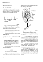
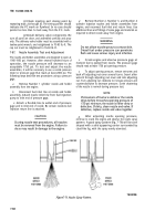
g.
After adjusting nozzle opening pressure,
continue to crank the engine and observe the nozzle spray
pattern. A good spray pattern (fig. 7-79) will be cone
shaped with a solid appearing center surrounded by
cloud-like fog, with the spray evenly atomized.
Figure
7-79. Nozzle
Spray Pattern.
7-68
Back to Top

