TM-9-2330-356-14
SEMITRAILER, TANK: 5000 GALLON, BULK HAUL, SELF LOAD/UNLOAD M967 AND M967A1; SEMITRAILER, TANK: 5000 GALLON, FUEL DISPENSING, AUTOMOTIVE M969 AND M969A1; SEMITRAILER, TANK: 5000 GALLON, FUEL DISPENSING, UNDER/OVERWING AIRCRAFT M970 AND M970A1
TECHNICAL MANUAL; OPERATOR’S, UNIT, DIRECT SUPPORT, AND GENERAL SUPPORT MAINTENANCE MANUAL
OCTOBER 1990
TM-9-2330-356-14 - Page 418 of 528
TM 9-2330-356-14
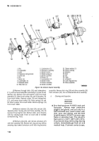
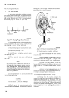
(17) Attach red and black leads (fig. 7-69) to
regulator (43, fig. 7-64). Attach blue regulator lead to
diode terminal screw by placing the spade terminal under
the head of the screw. Tighten nut on terminal screw
(fig. 7-64). Install regulator, and ensure that the red and
black leads are properly routed through their slots in the
regulator housing (37, fig. 7-64). Install the four screws to
fasten regulator in housing. Remove brush retaining pin
before tightening the screws.
(18) Install diode trio lead and nut.
NOTE
Due to the design of the alternator, a certain
amount of shaft end play will be present in
new or rebuilt units. This end play Is designed
Into the unit and will vary between .004- and
.012-inch.
(19) Install spacer (4), key (11), fan (3), pulley (2),
and nut (1). Tighten nut to 70-80 lb.-ft.
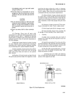
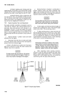
Figure
7-70.
Installing Brush Assemblies.
Section IV. TEST AND ADJUSTMENTS
7-80. General
a.
This section contains the test and adjustment
procedures that are required to be performed on a rebuilt
or repaired engine. These tests must be performed with
engine installed on semitrailer, and with batteries, control
boxes, fuel supply filters, and electrical supply hooked up
to the engine.
WARNING
Carbon monoxide is a colorless, odorless,
and deadly poisonous gas which occurs in
the exhaust fumes of the auxillary power en-
gine. Exposure to air contaminated with car-
bon monoxide produces symptoms of
headache, dizziness, loss of muscular con-
trol, apparent drowsiness, and coma. Perma-
nent brain damage or death can result from
severe exposure to carbon monoxide gas.
b.
Engine must be properly vented to exhaust the
engine to outside air. If possible, avoid sharp bends in
exhaust pipe or use sweeping, large radius elbows. Use a
section of seamless, flexible tubing between the engine
and any rigid pipe to restrict vibration. Increase exhaust
pipe one size larger for each additional 10 feet of length.
c.
For engine operating instructions, refer to
paragraph 2-10.
7-81.
Air Shutter Test and Adjustment
a.
Thermo Power Unit Assembly Test.
Immerse the
thermo unit (26, fig. 7-44) into a container of oil while
monitoring the oil temperature. Plunger of thermo unit
should start to extend when temperature reaches 120°F.
Total extension at 140°F should be at least 13/64-inch.
Replace thermo unit if it does not operate properly.
b.
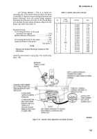
Adjustments.
(1)
Shutters (Fig. 7-71).
Disconnect ball joint
from upper shutter. Adjust ball joint until upper shutter
closes tightly on lower shutter when lower shutter is held
closed. Reattach ball joint to upper shutter.
7-62
Back to Top

