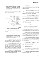
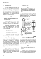
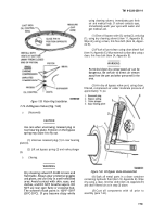
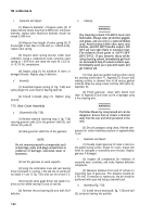
TM-9-2330-356-14
SEMITRAILER, TANK: 5000 GALLON, BULK HAUL, SELF LOAD/UNLOAD M967 AND M967A1; SEMITRAILER, TANK: 5000 GALLON, FUEL DISPENSING, AUTOMOTIVE M969 AND M969A1; SEMITRAILER, TANK: 5000 GALLON, FUEL DISPENSING, UNDER/OVERWING AIRCRAFT M970 AND M970A1
TECHNICAL MANUAL; OPERATOR’S, UNIT, DIRECT SUPPORT, AND GENERAL SUPPORT MAINTENANCE MANUAL
OCTOBER 1990
TM-9-2330-356-14 - Page 413 of 528
TM 9-2330-356-14
Immediately wash your eyes with water
and get medical aid.
Particles blown by compressed air can be
dangerous. Be sure to direct air stream
away from the user and other personnel in
the area.
CAUTION
Do not saturate armature or field coils with
solvent as wire Insulation may be dam-
aged. Do not dip drive assembly in solvent
as It Is packed in grease and cannot be re-
placed.
Never use emery cloth to clean commuta-
tor.
(1)
Cleaning.
Clean dust off parts with
compressed air or soft brush. Remove grease and oil with
dry cleaning solvent (item 11, Appendix E). Remove
discoloration or oxidation from commutator with fine
sandpaper grade 00. Clean off sand with compressed air.
Use only sandpaper.
(2)
Bearings.
Inspect bearing in pinion housing
for wear. Replace pinion housing (22) if bearing is
excessively worn. Inspect bearing in backplate assembly
(12). If excessively worn, replace backplate assembly.
(3)
Drive Assembly.
Inspect starter drive (29) for
cracks or chipped teeth. Ensure that shaft and spring
under drive moves freely and returns to rear position
when released.
(4)
Brushes.
Lift brush tension springs (14) and
lift each brush (20) from holder for inspection. Check
brush face for deep surface pits, cracks, or chipping.
Measure brush length. When brush is worn to less than
X-inch, replace. Clean the area around brushes and
commutator with dry, low pressure compressed air.
(5)
Solenoid Switch.
Inspect solenoid switch (9)
for cracks, dents, or other damage. Ensure that electrical
terminals are clean and free of corrosion. Check that the
rubber boot on the plunger and yoke is in good condition.
After installation, ensure that plunger and yoke move
freely.
(6)
Armature.
Inspect armature (27) for wear.
Inspect commutator for wear. If worn, replace starter.
(7)
Yoke.
Inspect yoke (26) for damage or wear.
(8)
Frame Assembly.
Inspect frame assembly (19)
for damage. If frame assembly is bad, replace starter.
c.
Assembly.
(1) Slide drive assembly (29) onto shaft of
armature (27). Install stop and lock ring (28) on end of the
armature shaft (27).
(2) Install thrust washer (21) on the end of the
armature shaft (27). Slip yoke (26) onto drive assembly
(29), and install both in pinion housing (22). Install pin (25)
in pinion housing (22) to hold yoke (26) in place.
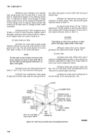
(3) If brushes (20) are excessively worn, cut brush
leads l-inch from the welded connection (fig. 7-63).
Install new brushes as follows:
(a)
Using rosin core solder and soldering
iron, or heavy duty soldering gun, tin the remaining
sections of the original brush lead.
Figure 7-63. Brush Replacement,
7-57
Back to Top

