TM-9-2330-356-14
SEMITRAILER, TANK: 5000 GALLON, BULK HAUL, SELF LOAD/UNLOAD M967 AND M967A1; SEMITRAILER, TANK: 5000 GALLON, FUEL DISPENSING, AUTOMOTIVE M969 AND M969A1; SEMITRAILER, TANK: 5000 GALLON, FUEL DISPENSING, UNDER/OVERWING AIRCRAFT M970 AND M970A1
TECHNICAL MANUAL; OPERATOR’S, UNIT, DIRECT SUPPORT, AND GENERAL SUPPORT MAINTENANCE MANUAL
OCTOBER 1990
TM-9-2330-356-14 - Page 407 of 528
TM 9-2330-356-14
NOTE
If the counterbore is damaged, it must be
machined for an oversized valve seat. Valve
seats are available in 0.005- and 0.010-inch
oversize diameters.
(d)
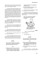
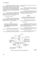
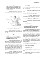
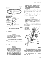
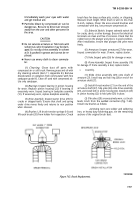
Cut valve seat to a narrow, 1/64-inch rind
(fig. 7-57) and remove rind using a
damage valve seat counterbore.
sharp tool. Do not
Figure 7-57, Removing Exhaustt Valve Seat.
(e)
Clean out valve scat counterbore, re-
move burrs from edges, and check counterbore diameter
(fig. 7-56).
the
NOTE
To facilitate valve seat installation, heat the
cylinder head in an oven at 325°F for
approximately thirty minutes and cool the
replacement valve seat in dry ice.
(f)
Install new replacement valve seat. Use
valve seat driver tool (table 5-1 and 14, fig. 7-55) to
ensure that valve seat sets evenly in the counterbore.
(g)
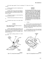
After installation, face each new valve
seat to a 45° angle for exhaust valve and a 42° angle for
intake valve, and a width of approximately 3/64- to 1/16-inch
(fig. 7-56). The finished seat face should contact
approximate center of valve face. Use Prussion Blue dye
(item 12, Appendix E) on the valve face to check contact
points with refaced valve seats. Make any corrections to
the valve seat, not the valve face.
(h)
Check
for 0.0300-inch minimum
clearance between valve head and cylinder head surface
(fig. 7-56). If necessary, regrind valve seat.
(4)
Valve Spring.
(a)
Inspect valve spring (5, fig. 7-55) for
evidence of damage. Replace spring if cracked, pitted, or if
ends are out-of-square.
(b)
Check valve spring for 1.875-inch free
length.
(c)
Inspect valve spring under load
conditions using a compression scale as follows:
1. Compress spring to 1.528-inch
(valve closed), and check scale for 45-49 lb. compression.
2. Compress spring to 1.182-inch
(valve open), and check scale for 87-97 lb. compression.
(d)
Discard springs that fail to meet above
requirements.
d.
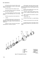
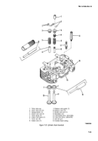
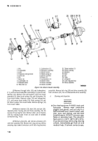
Assembly (Fig. 7-55).
NOTE
The valve stem seal assemblies (4) are
installed on the Intake valve guides only.
(1) Position a new replacement valve stem seal
assembly (4, fig. 7-55) on the intake valve guides only.
Apply a film of oil to inside surface of the valve stem seal.
(2) Apply a film of oil to the valve stem and insert
valve stem up into the valve guide. Check valve for tight
seal by making pencil marks at intervals on the valve face
and observe if pencil marks rub off uniformly when valve is
rotated 1/4 turn. If not a tight seal, regrind the valves.
(3) Using a valve spring compressor, compress
the valve spring (5) and spring retainer (3) sufficiently to
permit installation of the valve stem locks (2). Be certain
the valve spring locks are properly seated before releasing
the spring compressor.
(4) Repeat steps (1) through (3) to install
remaining intake and exhaust valve components.
7-73.
Piston and Connecting Rod
a.
Disassembly (Fig. 7-26).
(1) Usings ring expander, remove piston rings (1,
2, and 4, fig. 7-26) and oil ring expander (3) from each
piston.
(2) Remove two retaining
piston pin (6) from each piston.
rings (5) and push
7-51
Back to Top

