TM-9-2330-356-14
SEMITRAILER, TANK: 5000 GALLON, BULK HAUL, SELF LOAD/UNLOAD M967 AND M967A1; SEMITRAILER, TANK: 5000 GALLON, FUEL DISPENSING, AUTOMOTIVE M969 AND M969A1; SEMITRAILER, TANK: 5000 GALLON, FUEL DISPENSING, UNDER/OVERWING AIRCRAFT M970 AND M970A1
TECHNICAL MANUAL; OPERATOR’S, UNIT, DIRECT SUPPORT, AND GENERAL SUPPORT MAINTENANCE MANUAL
OCTOBER 1990
TM-9-2330-356-14 - Page 397 of 528
TM 9-2330-356-14
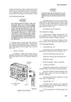
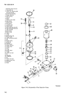
7-69. Fuel Injection Pump (Fig. 7-46)
(6) Remove the delivery valve holder(9), then lift
out the delivery valve spring (10), delivery valve (11),
a.
Disassembly (Fig. 7-46). All
work on injection
delivery valve body (42), and delivery valve spacer (12).
equipment MUST be performed in the cleanest location
possible. No filing, scraping, or sawing should be done on
(7) Remove the hydraulic head locating screw
the bench where repairs are made.
(13) and copper gasket (14).
WARNING
Dry cleaning solvent P-D-680 is toxic and
flammable. Always wear protective goggles
and gloves, and use only In a well-ventilated
area. Avoid contact with skin, eyes, and
clothes, and DO NOT breathe vapors. DO
NOT use near open flame or excessive heat.
The solvent’s flash point is 10O”F-138°F
(38°C-590°C). if you become dizzy while
using cleaning solvent, immediately get fresh
air and medical help. if solvent contacts eyes,
immediately wash your eyes with water and
get medical aid.
(1) Clean all external dirt and grease from the
pump.
CAUTION
The pump housing must NEVER be clamped
in a vise.
NOTE
(8) Remove four head retaining screws (15) and
four head retaining clamps (16). Carefully rest tappet on
clean surface and using shaft head, hammer pump body
assembly until hydraulic head assembly separates from
body assembly.
(9) Remove the O-rings (18 and 19) from the
hydraulic head and the pump housing.
(10) Remove the tappet (20) and related O-ring
(21) from the face gear bore.
(11) Remove the spring ring (22) and the plunger
button (23) from the end of the plunger (the plunger is
part of hydraulic head assembly).
(12) Invert the hydraulic head assembly and place
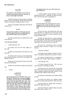
it in a suitable arbor press (fig. 7-47).
(13) Position tool TSE 76215 (table 5-1) over the
lower spring seat washer (24, fig. 7-46) and depress the
plunger spring, then remove the lower seat (25).
(14) Remove lower spring seat washer (24,
fig. 4-46) and plunger spring (26).
(15) Place the hydraulic head assembly on a
bench. Use two screwdrivers to pry off the face gear (28),
then remove the thrust washer (29).
A special mounting fixture (table 5-2) must be
made to adequately secure the pump
NOTE
housing.
The plunger, plunger sleeve and hydraulic
head are mated parts and must always be
(2) Clamp the mounting fixture in a suitable vise.
kept together.
-
(16) Do not remove the plunger (35) from the
(3) Install the pump housing into the mounting hydraulic head
fixture with two two - 18 UNC hex head screws.
(4) Release lock tabs (2) and remove the two
control unit retaining plate screws (1), tab washers (2,
fig. 7-46), and the control unit retaining plate and stop
assembly (3). Carefully pull the control unit assembly (4)
with plunger sleeve pin (5) out of the pump housing (6).
Plunger sleeve pin Occasionally may have to be removed
separately. Use needle nose pliers or magnetic pencil.
(5) Remove the delivery valve cap nut (7) and
gasket (8).
b.
Inspection (Fig. 7-46).
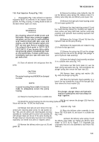
(1) Place the delivery valve assembly in test
fixture TSE 76226 (table 5-l), and secure in a suitable vise
(fig, 7-48).
(a)
Insert the delivery valve spring (1) and
the delivery valve holder (2). Tighten the delivery valve
holder to 70-75 Ib.-ft. Figure 7-77 illustrates the
components that are to be assembled to test fixture TSE
76226 (3).
7-41
Back to Top

