TM-9-2330-356-14
SEMITRAILER, TANK: 5000 GALLON, BULK HAUL, SELF LOAD/UNLOAD M967 AND M967A1; SEMITRAILER, TANK: 5000 GALLON, FUEL DISPENSING, AUTOMOTIVE M969 AND M969A1; SEMITRAILER, TANK: 5000 GALLON, FUEL DISPENSING, UNDER/OVERWING AIRCRAFT M970 AND M970A1
TECHNICAL MANUAL; OPERATOR’S, UNIT, DIRECT SUPPORT, AND GENERAL SUPPORT MAINTENANCE MANUAL
OCTOBER 1990
TM-9-2330-356-14 - Page 390 of 528
TM 9-2330-356-14
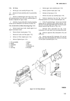
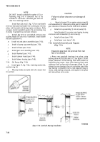
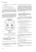
7-49. Oil Filter Adapter (Fig. 7-20)
a.
Clean all gasket material from oil filter adapter
(19, fig. 7-20) and cylinderblock. Attach oil filter adapter
(19) and new gasket (20) to cylinder block with three
capscrews (17) and lockwashers (18). Tighten capscrews to
45-50 lb.-ft.
b.
Attach all oil lines to oil filter adapter
(para 7-50).
c.
Install oil filter (para
4-72).
d.
Install elbow (15). Tighten
position 90° right of top center.
elbow securely to
e.
Attach oil cooler hoses 10 oil filter adapter
(para 7-59).
f
Replace blower housing (para 7-60).
7-50. Oil Lines (Fig. 7-20)
c .
a.
b.
tee (3).
tee(3).
d.
adapter
7-51.
a.
sides of
b.
c.
Connect oil line (6, fig. 7-20) to elbow (7).
Connect oil line (4) to adapter (5) and restricted
Connect oil line (2) to adapter (1) and restricted
Connect oil line (9) to elbow (10) on oil filter
(19) and restricted tee (14).
Oil Filler Tube (Figs. 7-18 and 7-19)
Apply adhesive (item 2, Appendix E) to both
new gasket (4, fig 7-19).
Position gasket (4) on filler tube (3).
Position both gasket and filler tube on engine
crankcase. Install two capscrews (1) and lockwashers (2),
and tighten.
d.
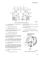
Position fuel filter adapter (1, fig. 7-18) and fuel
filters (2) onto engine crankcase. Install three capscrews
(3) and lockwashers (4), and tighten.
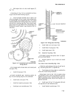
7-52. Exhaust Manifold (Fig. 7-17)
a.
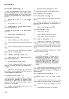
Install exhaust manifold (4) and four new gaskets
(5) to cylinder heads. Secure with four lock tabs (1), eight
capscrews (2), and eight washers (3). Tighten capscrews
evenly to 13–15 lb.-ft. Bend lock tabs (1) up to prevent
capscrews (2) from loosening.
b.
Replace high temperature switch (para 7-57).
Replace exhaust pipe (para 4-77).
c.
Replace air shutter assembly (para 7-60),
7-53. Engine Junction Box and Electrical Wiring
Refer to paragraph 4-19 for installation.
7-54. Fuel Stop Solenoid (Fig. 7-16)
a.
Connect lead from control switch terminal on
solenoid.
b.
Position solenoid on bottom cylinder pan and
install two screws. Be sure ground lead is installed by one
of the screws.
c.
Adjust solenoid plunger (para 7-85).
7-55. Fuel Lines (Fig. 7-15)
a.
Install injector lines (7).
b.
Install manifold (4) and return lines (5).
c.
Install injector nozzle return lines (3).
7-56.
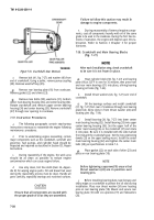
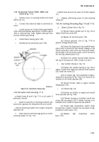
Governor Linkage (Fig. 7-1 4)
a.
Using screws (13), lockwashers (14), and nuts (15),
attach governor control bracket (12) to engine backplate.
b.
Insert end of throttle rod (7) through two washers
(20) and into hole in control arm (19). Secure with cotter
pin (5).
c.
Attach throttle cable (11) to throttle arm (10)with
clevis pin (9) and cotter pin (8).
NOTE
If new ball joints are used on linkage, position
the new joints to obtain the same length or
1/32 inch more than the old linkage (one turn
equals 1/32 inch). If old linkage
length
is
not
available, position new ball
joints about
midway on each end of linkage, then lengthen
1/8-inch.
d.
Attach governor arm (3) to governor shaft (4) and
install spring (17). Attach opposite end of governor arm to
governor linkage (1). Connect governor linkage (1) to
injector pump (2).
7-57.
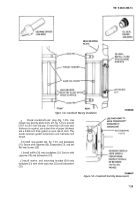
High Temperature Switch (Fig. 7-1 3)
a.
Assemble items 5-13 in order shown in figure
7-13.
b.
Install assembled pressure switch by securing
switch bracket (10) with two capscrews (3) and washers(4).
c.
Connect two leads (1 and 2) to high temperature
switch.
d.
Remove block from louvers on air shutter.
7-34
Back to Top

