TM-9-2330-356-14
SEMITRAILER, TANK: 5000 GALLON, BULK HAUL, SELF LOAD/UNLOAD M967 AND M967A1; SEMITRAILER, TANK: 5000 GALLON, FUEL DISPENSING, AUTOMOTIVE M969 AND M969A1; SEMITRAILER, TANK: 5000 GALLON, FUEL DISPENSING, UNDER/OVERWING AIRCRAFT M970 AND M970A1
TECHNICAL MANUAL; OPERATOR’S, UNIT, DIRECT SUPPORT, AND GENERAL SUPPORT MAINTENANCE MANUAL
OCTOBER 1990
TM-9-2330-356-14 - Page 395 of 528
TM 9-2330-356-14
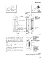
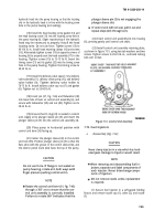
shutters and shutter box sides is maintained and that
brackets (4) are seated against shoulder of bearings (7)
prior to tightening screws (1) and nuts (2). Check shutters
to ensure that they fully open and close without bending.
7-65. Oil Cooler and Lines
WARNING
Dry cleaning solvent P-D-680 is toxic and
flammable, Always wear protective goggles
and gloves, and use only in a well-ventilated
area. Avoid contact with skin, eyes, and
clothes, and DO NOT breathe vapors. DO
NOT use near open flame or excessive heat.
The solvent’s flash point is 100”F-138°F
(38°C-590°C). If you become dizzy while
using cleaning solvent, immediately get fresh
air and medical help. If solvent contacts eyes,
immediately wash your eyes with water and
get medlical aid.
a.
Cleaning.
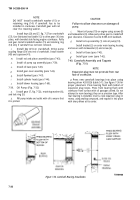
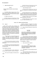
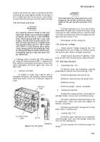
Clean oil cooler (fig, 7-45) inside and
out
using dry cleaning solvent (item 11, Appendix E).
Flush piping by forcing diesel fuel through oil cooler inlet.
Drain thoroughly and flush again with clean oil
(para 7-62).
b.
Inspection and Repair.
(1) Inspect on cooler (fig. 7-45) for bent or
damaged cooling fins, and cracked or defective welds
which may result in loss of oil. If defective, replace oil
cooler.
TA100116
Figure 7-45. Oil Cooler.
WARNING
Particles blown by compressed air can be
dangerous. Be certain to direct air stream
away from the user and other personnel in the
area.
(2) Using compressed air at 15 psi, test oil cooler
under water for leaks. Dry outside of oil cooler using
compressed air under moderate pressure, and flush inside
of oil cooler using diesel fuel. Drain thoroughly and flush
again with clean oil (para 7-62).
(3) Straighten all bent cooling fins.
7-66. Governor Linkage
a.
Inspect governor linkage components (fig. 7-14)
for damaged threads, bent linkage rod, defective spring,
and excessive wear. Replace damaged components.
b.
Inspect snap-in ball joints for tightness. If ball
joints are worn and come apart easily, replace ball joints.
7-67. Fuel Stop Solenoid
a.
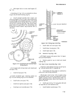
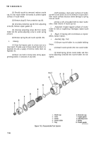
Disassembly (Fig. 7-16).
(1) Remove screw and lockwasher securing
ground lead to solenoid, and remove lead (fig. 7-16).
(2) Remove adjusting screw and jam nut.
(3) Remove retaining rings and plunger cover.
(4) Remove spring.
(5) Remove plunger, retainer, and gasket.
b.
Cleaning and Inspection.
(1) Wipe all components clean, and inspect for
damaged threads, excessive wear, and defective spring.
(2) Inspect waterproof solenoid plunger cover
for deterioration, cracks, and small holes. Replace all
defective components.
(3) Inspect ground lead for damage due to sharp
bends, kinks, or excessive wear.
c.
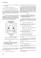
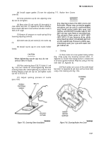
Assembly (Fig. 7-16).
(1) Position upper retaining ring in waterproof
solenoid plunger cover, and insert plunger spring into
cover over the retaining ring.
(2) Insert grooved end of solenoid plunger into
retainer.
7-39
Back to Top

