TM-9-2330-356-14
SEMITRAILER, TANK: 5000 GALLON, BULK HAUL, SELF LOAD/UNLOAD M967 AND M967A1; SEMITRAILER, TANK: 5000 GALLON, FUEL DISPENSING, AUTOMOTIVE M969 AND M969A1; SEMITRAILER, TANK: 5000 GALLON, FUEL DISPENSING, UNDER/OVERWING AIRCRAFT M970 AND M970A1
TECHNICAL MANUAL; OPERATOR’S, UNIT, DIRECT SUPPORT, AND GENERAL SUPPORT MAINTENANCE MANUAL
OCTOBER 1990
TM-9-2330-356-14 - Page 387 of 528
TM 9-2330-356-14
b.
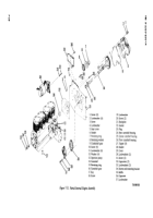
With engine laid on its side, install tappets (27,
fig. 7-31).
c.
Install key (17, fig. 7-31) on camshaft (14). Press
on gear (16) and install retaining ring (15).
d.
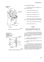
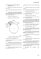
Install camshaft assembly (14) in engine, and
ensure that tappets (27) are in place. Aline timing marks
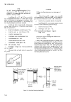
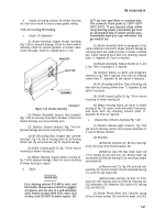
on camshaft gear and crankshaft gear (fig. 7-37). Install
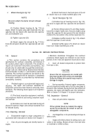
retaining washer (8) and retaining ring (7). Use a pinch bar
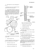
and pry up on crankcase gear (fig. 7-28). Using a feeler
gage, measure the gap between the camshaft gear and
crankshaft retainer washer. Gap should be .007- to
.039-inches.
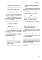
TA502325
Figure
7-37. Crankshaft and Camshaft Gear
Timing Marks.
e.
Turn engine with oil base down and install push
rods (para 7-43).
f.
Install oil base (para 7-43).
g.
Install crankshaft gear retaining washer (8,
fig. 7-31) and retaining ring (7) on the crankshaft.
h.
Install rocker arms (para 7-44).
i.
Install fuel injection pump (para 7-48).
j.
Install gear cover assembly (para 7-42).
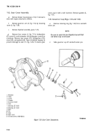
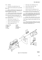
Figure 7-38. Timing Gear End Play.
k.
Install reeker arm covers (para 7-45).
l
Install blower housing (para 7-60).
m.
Install engine (para 5-20).
7-41.
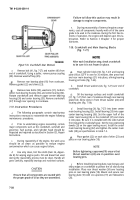
Governor Cup (Fig. 7-30)
TA502326
a.
Fill flyball recesses with grease (item 16, Appen-
dix E) and install flyballs.
b.
Position governor cup on shaft and install
retaining ring.
7-42. Gear Cover Assembly (fig. 7-28)
a.
Pack the cavity between the two oil seal lips (6,
fig. 7-28) with grease (item 16, Appendix E).
b.
Tape keyway and sharp edges on crankshaft to
protect the oil seal during installation.
c.
Mount gear cover (5, fig. 7-31) on engine using
new gasket(6), screws (1 and 3), and lockwashers (2 and 4).
Tighten mounting screws to specified torque (table 7-3).
Before tightening screws, ensure that stop pin is in
governor cup hole.
d.
Install cover (29, fig. 7-31) and gasket (28) with
two capscrews (31) and lockwashers (30).
e.
Install flywheel assembly (para 7-47).
7-31
Back to Top

