TM-9-2330-356-14
SEMITRAILER, TANK: 5000 GALLON, BULK HAUL, SELF LOAD/UNLOAD M967 AND M967A1; SEMITRAILER, TANK: 5000 GALLON, FUEL DISPENSING, AUTOMOTIVE M969 AND M969A1; SEMITRAILER, TANK: 5000 GALLON, FUEL DISPENSING, UNDER/OVERWING AIRCRAFT M970 AND M970A1
TECHNICAL MANUAL; OPERATOR’S, UNIT, DIRECT SUPPORT, AND GENERAL SUPPORT MAINTENANCE MANUAL
OCTOBER 1990
TM-9-2330-356-14 - Page 384 of 528
TM 9-2330-356-14
Failure to follow this caution may result In
damage to engine components.
e.
During reassembly of internal engine compo-
nents, coat all components heavily with oil of the same
grade to be used in the crankcase. During the first few mo-
ments of operation, the engine will depend upon this lu-
brication. Refer to Section I Chapter 3 for proper
lubricants.
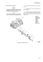
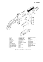
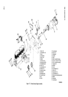
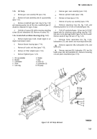
7-38. Crankshaft and Main Bearing Blocks
(fig. 7-27)
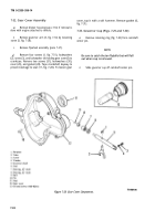
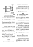
After each Installation step, check crankshaft
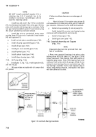
Figure
7-33.
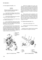
Cra.nhshaft Gear Removal.
to be sure it is not frozen In place.
o.
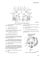
Remove bolt (41, fig. 7-27) and washer (40) from
end of crankshaft. Using a puller, remove pump coupling
(39). Remove woodruff key (25).
Remove rear bearing plate (18) from crankcase.
Remove gasket (22) and shims (23).
Remove two bolts (30), washers (31), bottom
center main bearing housing (32), and center bearing (34).
Rotate crankshaft and remove upper center bearing
housing (36) and center bearing (35). Remove crankshaft
(37) through rear opening in crankcase.
7-37. Instruction Procedures
a.
The following paragraphs contain step-by-step
instructions necessary to reassemble the engine following
maintenance procedures.
b.
Prior to undertaking engine reassembly, certain
major components such as the crankshaft, camshaft and
governor, fuel pumps, and cylinder head should be
inspected and repaired as described in Section III, Repair
Instructions.
c.
During reassembly of the engine, the work area
should be as clean as possible to reduce engine
contamination which can cause engine failure.
d.
Use only clean, lint free cloth (item 24, Appen-
dix E) for wiping engine parts. Oil and diesel fuel used
during the reassembly process must be clean. Handle all
parts carefully, especially bearings and machined surfaces.
CAUTION
Ensure that all components are coated with
the proper grade of oil as they are assembled.
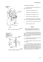
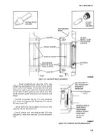
Heat cylinder block (38, fig. 7-27) and bearing
plate (18) at 325°F in oven for 30 minutes, then press front
and rear main bearings (21) into place, alining bearing
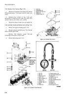
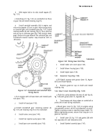
housing oil holes (fig. 7-34).
b.
Install thrust washers (24, fig. 7-27) over end of
crankshaft.
Oil the bearings surfaces and install crankshaft
(37, fig. 7-27) from rear of crankcase through rear bearing
plate hole. Aline slots in front thrust washer (24) with
locating pins (fig. 7-34).
d.
Install bearing (34, fig. 7-27) into lower center
main bearing housing (32). Install bearing (35) into upper
center bearing housing (36). Set the upper half of the
center main housing (36) on the crankshaft (37) and rotate
it into place. Be sure it is installed with the side marked
front toward the crankshaft gear. Set the two positioning
dowels (33) on the upper bearing mount. Install the center
main bearing housing (32) and tighten the center main
bolts (30) per specifications in table 7-3.
Place gasket (22) on each side of shim (23) and
place on rear bearing plate (18).
NOTE
Before tightening capscrews(19) ensure that
thrust washers (24) are in position over
locating pins.
f.
Before installing bearing plate, tape keyway and
sharp edges on crankshaft to protect the oil seal during
installation. Place rear thrust washer (24) over locating
pins on rear bearing plate (18). Mount and secure rear
bearing plate (18) with six capscrews (19) and flatwashers
(20).
7-28
Back to Top

