TM-9-2330-356-14
SEMITRAILER, TANK: 5000 GALLON, BULK HAUL, SELF LOAD/UNLOAD M967 AND M967A1; SEMITRAILER, TANK: 5000 GALLON, FUEL DISPENSING, AUTOMOTIVE M969 AND M969A1; SEMITRAILER, TANK: 5000 GALLON, FUEL DISPENSING, UNDER/OVERWING AIRCRAFT M970 AND M970A1
TECHNICAL MANUAL; OPERATOR’S, UNIT, DIRECT SUPPORT, AND GENERAL SUPPORT MAINTENANCE MANUAL
OCTOBER 1990
TM-9-2330-356-14 - Page 386 of 528
TM 9-2330-356-14
NOTE
DO NOT install crankshaft washer (15) or
retaining ring (14) if camshaft has to be
installed in crankcase. Camshaft gear will not
clear the retaining washer.
Install keys (26 and 27, fig. 7-27) on crankshaft
(37), Use fabricated tool (table 5-2) to drive gear (16) into
place, with beveled side facing engine crankcase. Fully
seat gear. Install crankshaft washer (15) and retaining ring
(14) only if camshaft has not been removed.
l.
Install key (25) on crankshaft. Drive pump
coupling flange (39) onto end of crankshaft. Install washer
(40) and capscrew (41).
m.
n.
o.
p.
q.
r.
s.
7-39.
a.
Install rod and piston assemblies (para 7-43).
Install oil pump cup assembly (para 7-39).
Install oil base (para 7-43).
Install gear cover assembly (para 7-42).
Install flywheel (para 7-47).
Install cylinder heads (para 7-44).
Install blower housing (para 7-60).
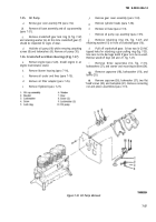
Oil Pump (Fig. 7-32)
Install gear (7, fig. 7-32), retaining washer (6),
and lock ring (5).
b.
Fill pump intake and outlet with oil to ensure that
it is primed.
CAUTION
Fallure to allow clearance can damage oil
pump.
c.
Mount oil pump (10) on engine using screws (8)
and lockwashers (9). Allow pump drive gear to crankshaft
gear clearance. Clearance must be 0.005-inch backlash.
d.
Install oil cup assembly (1) into oil pump (10).
Install bracket (2) on center main bearing housing
and secure with lockwasher (3) and screw (4).
f.
Install oil base (para 7-43).
g
Install gear cover (para 7-42).
7-40. Camshaft Assembly and Tappets
(Fig. 7-31)
NOTE
Expansion plug must not protrude from rear
face of crankcase.
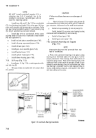
a.
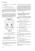
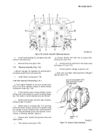
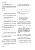
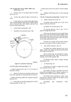
Press new camshaft bearings into place using
bearing driver 420-0326 (table 5-1). See figure 7-36 for
proper placement. Press bearing flush with bottom of
expansion plug recess. Press front bearing flush with
crankcase front surface with oil passages alined. Do not
attempt to ream bearings; they are a precision type. After
rear bearing is installed, insert a new expansion plug in
recess, using sealing compound, and expand it into place
with sharp blows at its center.
Figure 7-36. Camshaft Bearing Installation.
7-30
Back to Top

