TM-9-2330-356-14
SEMITRAILER, TANK: 5000 GALLON, BULK HAUL, SELF LOAD/UNLOAD M967 AND M967A1; SEMITRAILER, TANK: 5000 GALLON, FUEL DISPENSING, AUTOMOTIVE M969 AND M969A1; SEMITRAILER, TANK: 5000 GALLON, FUEL DISPENSING, UNDER/OVERWING AIRCRAFT M970 AND M970A1
TECHNICAL MANUAL; OPERATOR’S, UNIT, DIRECT SUPPORT, AND GENERAL SUPPORT MAINTENANCE MANUAL
OCTOBER 1990
TM-9-2330-356-14 - Page 383 of 528
TM 9-2330-356-14
7-35.
Oil Pump
a.
Remove gear cover assembly TM (para 7-32).
Remove oil base assembly and oil cup assembly
(para 7-31).
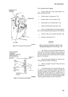
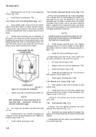
Remove crankshaft gear lock ring (5, fig. 7-32)
and retaining washer (6). At this time crankshaft gear (7)
should be inspected for signs of wear.
d.
Hold the oil pump (10) while removing attaching
screws (8) and lockwashers (9). Remove oil pump (10).
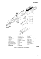
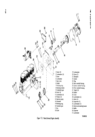
7-36. Crankshaft and Main Bearings (Fig. 7-27)
a.
Remove engine (para 5-20). Install engine in an
engine maintenance stand.
b.
Remove blower housing (para 7-14),
c.
Remove oil cooler and lines (para 7-15).
d.
Remove oil filter adapter (para 7-25).
e.
Remove flywheel (para 7-27).
f
Remove gear cover assembly (para 7-32).
g.
Remove cylinder heads (para 7-30),
h.
Remove oil base (para 7-31).
1.
Remove oil pump cup assembly (para 7-35).
Remove retaining ring (14, fig. 7-27) and
retaining washer (15) in front of crankshaft gear (16).
k.
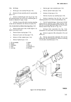
Pull off crankshaft gear. It has two ¼-20 NC
tapped holes for attaching a gear pulling ring (fig. 7-33).
Use care not to damage teeth if gear is to be re-used.
Remove woodruff keys (26 and 27, fig, 7-27).
1.
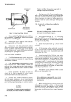
Remove three capscrews (32, fig. 7-31),
lockwashers (37), and starter and mounting bracket (34).
Remove capscrew (18), lockwasher (19), and
baffle (35).
Remove capscrew (36), lockwasher (37), two flat
head screws (20), and backplate (21). Remove connecting
rod and piston assemblies (para 7-31).
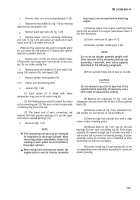
Figure 7-32. Oil Pump Removal.
7-27
Back to Top

