TM-9-2330-356-14
SEMITRAILER, TANK: 5000 GALLON, BULK HAUL, SELF LOAD/UNLOAD M967 AND M967A1; SEMITRAILER, TANK: 5000 GALLON, FUEL DISPENSING, AUTOMOTIVE M969 AND M969A1; SEMITRAILER, TANK: 5000 GALLON, FUEL DISPENSING, UNDER/OVERWING AIRCRAFT M970 AND M970A1
TECHNICAL MANUAL; OPERATOR’S, UNIT, DIRECT SUPPORT, AND GENERAL SUPPORT MAINTENANCE MANUAL
OCTOBER 1990
TM-9-2330-356-14 - Page 389 of 528
TM 9-2330-356-14
TA100112
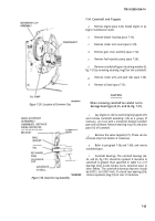
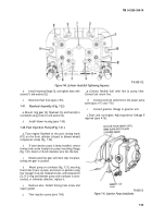
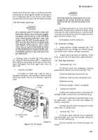
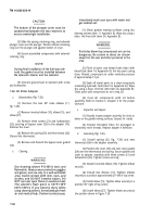
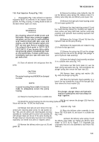
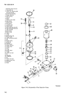
Figure 7-40. Cylinder Head Bolt Tightening Sequence.
d.
Install retaining flange (3), and tighten down with
screws (1) and washers (2).
e.
Reconnect fuel lines (para 7-55).
7-47.
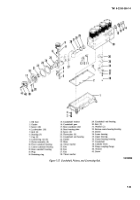
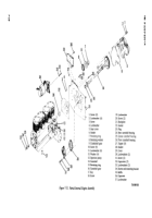
Flywheel Assembly (Fig. 7-22)
a.
Mount ring gear (5), flywheel (3), and hub (4) to
crankshaft using screw (1) and washer (2).
b.
Install blower housing (para 7-60).
7-48. Fuel Injection Pump (Fig. 7-21 )
a.
Tune engine flywheel to the port closing mark
(PC) on the front cylinder (closest to blower wheel)
compression stroke (fig. 7-78).
b.
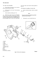
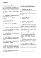
If new injection pump is being installed, remove
timing hole screw located on pump mounting flange
(fig. 7-41). Insert a 1/8-inch diameter wire into the hole.
c.
Rotate pump face gear until wire slips into place,
locking the gear in position.
d.
Mount pump on crankcase (fig. 7-21), ensuring
that shims (5) are in place, and secure in position using
four hexagon nuts (2), flatwashers (4), and lockwashers
(3). If O-ring seal between pump and crankcase is worn,
cracked, or otherwise defective, replace it.
e.
Remove wire. Install timing hole screw and
copper gasket.
f.
Time injection pump (para 7-86).
g.
Connect flexible fuel inlet line to pump inlet.
Connect fuel return line.
h
Connect each fuel outlet line to the proper pump
outlet (para 4-73 and 7-55)
i.
Connect governor linkage to governor arm.
j.
Start and run engine. Adjust governor linkage if
required (para 4-76).
TA100113
Figure 7-41. Injection Pump Installation.
7-33
Back to Top

