TM-9-2330-356-14
SEMITRAILER, TANK: 5000 GALLON, BULK HAUL, SELF LOAD/UNLOAD M967 AND M967A1; SEMITRAILER, TANK: 5000 GALLON, FUEL DISPENSING, AUTOMOTIVE M969 AND M969A1; SEMITRAILER, TANK: 5000 GALLON, FUEL DISPENSING, UNDER/OVERWING AIRCRAFT M970 AND M970A1
TECHNICAL MANUAL; OPERATOR’S, UNIT, DIRECT SUPPORT, AND GENERAL SUPPORT MAINTENANCE MANUAL
OCTOBER 1990
TM-9-2330-356-14 - Page 396 of 528
TM 9-2330-356-14
CAUTION
The bottom of the plunger cover must be
sandwiched between the two retainers to
ensure a watertight installation.
(3) Slide the spring, retaining ring, and solenoid
plunger cover over the plunger. Position bottom retaining
ring over the plunger and against bottom of cover.
(4) Secure assembled components with external
retaining ring.
NOTE
During final installation of the fuel stop sole-
noid, the gasket must be installed between
the solenoid retainer and the solenoid.
(5) Connect ground lead to solenoid with screw
and lockwasher.
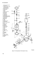
7-68. Oil Filter Adapter
a.
Disassembly (Fig. 7-20).
(1) Remove the two 90° tube elbows (11,
fig. 7-20).
(2)
Remove inverted elbow (10), elbow (15), and
elbow (27).
(3) Remove three screws (21) and lockwashers
(22) securing oil bypass cover (23) to the adapter (19).
Remove the cover.
(4) Remove the spring (25) and thermostat (26).
Discard the thermostat.
(5) Remove and discard the bypass cover gasket
(24).
b.
Cleaning.
WARNING
Dry cleaning solvent P-D-680 is toxic and
flammable. Always wear protective goggles
and gloves, and use only in a well-ventilated
area. Avoid contact with skin, eyes, and
clothes, and DO NOT breathe vapors. DO
NOT use near open flame or excessive heat.
The solvent’s flash point is 100°F-138°F
(38°C-590°C). if you become dizzy while
using cleaning solvent, Immediately get fresh
air and medical help. If solvent contacts eyes,
immediately wash your eyes with water and
get medical aid.
(1) Clean gasket mating surfaces using dry
cleaning solvent (item 11, Appendix E). Wipe dry using a
clean, lint-free cloth (item 24, Appendix E).
WARNING
Particles blown by compressed air can be
dangerous. Be certain to direct air stream
away from the user and other personnel in the
area.
(2) Flush oil ports and thread holes clean with
diesel fuel (item 14, Appendix E). Air dry ports using
clean, filtered, compressed air under moderate pressure
of approximately 15 psi.
(3) Soak all metal parts in a clean receptacle
containing hydraulic fluid (item 18, Appendix E). Wipe
dry using a clean, lint-free cloth (item 24, Appendix E).
Clean parts with compressed air as in step (2).
(4) Coat all components with oil before
assembly. Refer to Section I, Chapter 3 for the proper
lubricant.
c.
Inspection and Repair.
(1) Visually inspect adapter assembly for nicks or
dents on the gasket mating surfaces. Inspect for cracks.
(2) Inspect threaded holes for damaged or
excessively worn threads. Replace adapter if defective.
d.
Assernbly (Fig.
7-20).
(1) Install spring (25, fig. 7-20) and new
thermostat (26) in the adapter assembly.
(2) Position the cover (23) and new cover gasket
(24) over the thermostat and spring. Secure gasket and
cover to adapter assembly with three screws (21) and
lockwashers (22). Tighten screws securely.
(3) Install inverted elbow (10). Tighten elbow
securely.
(4) Install two elbows (11). Tighten elbows
securely to a position approximately 20° left of top center.
(5) Install elbow (15). Tighten elbow securely to a
position 90° right of top center.
(6) Install elbow (27). Tighten elbow securely to
the position shown in figure 7-20.
7-40
Back to Top

