TM-9-2330-356-14
SEMITRAILER, TANK: 5000 GALLON, BULK HAUL, SELF LOAD/UNLOAD M967 AND M967A1; SEMITRAILER, TANK: 5000 GALLON, FUEL DISPENSING, AUTOMOTIVE M969 AND M969A1; SEMITRAILER, TANK: 5000 GALLON, FUEL DISPENSING, UNDER/OVERWING AIRCRAFT M970 AND M970A1
TECHNICAL MANUAL; OPERATOR’S, UNIT, DIRECT SUPPORT, AND GENERAL SUPPORT MAINTENANCE MANUAL
OCTOBER 1990
TM-9-2330-356-14 - Page 401 of 528
TM 9-2330-356-14
hydraulic head into the pump housing so that the locating
slot in the hydraulic head is in line with the locating screw
hole in the pump housing (not seating).
(16) Install the head locating screw gasket (14) and
the head locating screw (13) into the locating screw hole in
the pump housing (6). Slight repositioning of the hydraulic
head may be necessary to properly install the head
locating screw. Do not use force. Tighten screw (13) to
90-100 lb.-in. Install head retaining clamps (16) and screws
(15). Alternately tighten screws (15) at opposite comers of
housing (6) to properly seat the head assembly (17) in the
housing. Tighten screws (15) to 13-15 lb.-ft. Insert the
timing screw (31) and its gasket (32) into the timing screw
hole in the pump housing. Tighten the timing screw to
20-25 lb.-in.
(17) Install the delivery valve spacer (12), delivery
valve assembly (11), delivery valve spring (10), and delivery
valve holder (9). Tighten delivery valve holder to
70-75 lb.-ft. Install delivery valve cap nut (7) and gasket
(8). Tighten nut to 55-60 lb.-ft.
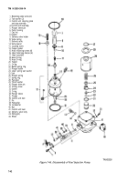
(18) Insert pin (37, fig. 7-46) and flatwasher (38)
into lower hole of lever on control unit assembly (4), and
secure with lockwasher (39) and nut (40). Tighten nut to
20-25 lb.-in.
(19) Ensure that O-ring (33) is seated in control
unit. Apply oil to plunger sleeve pin (5) and insert the
plunger sleeve pin (5) into the control unit assembly (4).
(20) Place pump in horizontal position with
control unit bore (36) facing up.
(21) Center the plunger sleeve (34) in the control
unit bore (36). Position plunger sleeve pin (5) so that the
flats aline with the groove in the control sleeve (34), and
the electric pencil mark (dot) faces the top of the pump.
CAUTION
Do not use force. If flange is not seated on
pump housing, rotate arm both ways with
finger pressure pushing control unit in.
NOTE
Rotate the control unit lever (41, fig. 7-46)
through a 360° arc to ensure that the con-
trol unit assembly is correctly installed.
Failure to rotate 360° Indicates that the
plunger sleeve pin (5) is not engaging the
plunger sleeve slot.
If control unit will not seat, pull it out and
repeat steps (20) through (22).
(22) Insert control unit assembly (4) into housing
(6), pressing gently until control unit seats.
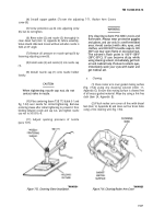
(23) Install control unit assembly retaining plate,
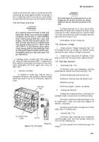
as shown in figure 7-51, using two tab washers and two
screws. Tighten screws to 20-25 lb.-in., and bend locking
tabs over screws.
Figure 7-51.
Control Unit Assembly.
7-70. Fuel Injectors
a.
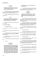
Disassembly (Fig. 7-52).
CAUTION
Never clamp injector in a vise which has hard-
ened jaws. Damage to Injector would result.
NOTE
When removing and disassembling fuel in-
jectors, separate and label components of
each injector. Never Interchange compo-
nents of injectors.
DO not remove nozzle unless replacement
is required.
(1) Secure fuel injector in a soft-jawed holding
fixture, and remove nozzle cap (1), valve (2), and nozzle
(3).
7-45
Back to Top

