TM-9-2330-356-14
SEMITRAILER, TANK: 5000 GALLON, BULK HAUL, SELF LOAD/UNLOAD M967 AND M967A1; SEMITRAILER, TANK: 5000 GALLON, FUEL DISPENSING, AUTOMOTIVE M969 AND M969A1; SEMITRAILER, TANK: 5000 GALLON, FUEL DISPENSING, UNDER/OVERWING AIRCRAFT M970 AND M970A1
TECHNICAL MANUAL; OPERATOR’S, UNIT, DIRECT SUPPORT, AND GENERAL SUPPORT MAINTENANCE MANUAL
OCTOBER 1990
TM-9-2330-356-14 - Page 400 of 528
TM 9-2330-356-14
(6) Rotate lever (41) while holding sleeve of
control unit assembly (4). Shaft must turn freely. If a
binding condition exists, wash assembly in a cleaning
agent, and repeat procedure. If binding condition is still
present, injection pump must be replaced. Also ensure
that weld holding lever to shaft is intact.
(7) The flat end of plunger sleeve pin (5) must be
checked for clearance in the mating slot of the plunger
sleeve. If the clearance is greater than 0.0015-inch, the
injection pump must be replaced.
c.
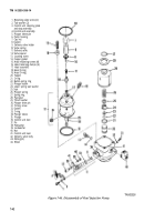
Reassembly (Fig.
7-46).
CAUTION
Be careful not to damage O-ring gaskets.
(1) After all parts have been thoroughly cleaned
and inspected, dip the individual parts in clean diesel fuel
(item 14, Appendix E).
(2) Invert the hydraulic head (17, fig. 7-46) and
place it on a clean bench so that the head locating slot is
forward.
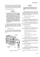
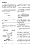
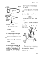
(3) Aline the plunger drive pin (1, fig. 7-50) into
the plunger (2) so that the head of the plunger drive pin is
in line with the distributor slot. Turn the plunger drive pin
until its long side is parallel to the length of the plunger
with long end up.
LONG SIDE OF HEAD PIN
1. Plunger drive pin
MUST BE PARALLEL TO
2. Plunger
LENGTH OF PLUNGER
3. Hydraulic head
AND UPWARD
4. Plunger sleeve
TA100121
Figure
7-50.
Assembling Hydraulic Head.
(4) Apply a thin coat of petrolatum (item 23,
Appendix E) to the thrust washer (29, fig. 7-46) and
assemble it to the hub on the face gear (28).
(5) Carefully center spring ring (27) on hydraulic
head assembly.
(6) Position the face gear (28) and thrust washer
(29) over the end of the plunger (35), and aline the head of
the plunger sleeve pin (5) with its mating slot located on
the inside of the face gear (28).
CAUTION
Do not use extreme pressure. If gear will not
snap Into place easily, remove gear and
check to see that spring ring (27) Is centered,
and that plunger drive pin (1, fig. 7-50) is
properly alined.
(7) Press the face gear (28, fig. 7-46) onto the
hydraulic head (17). Ensure that the spring ring (27) snaps
into its mating groove in the face gear (28). Manually
operate the plunger up and down. Free movement of the
plunger indicates that the face gear has been correctly
assembled to the hydraulic head.
(8) With head still in an inverted position, raise
plunger (35) to its highest position.
(9) Apply grease (item 17, Appendix E) to
exposed portion of plunger to keep it in its highest
position.
(10) Install spring (26) and spring retaining washer
(24). Snap spring seat (25) into place on the head of
plunger (35).
(11) Install the plunger button (23) onto the end of
the plunger and secure it by snapping the spring ring (22)
into its mating groove in the lower spring seat (25).
(12) Ensure that the button spring ring (22) fits
tightly into its groove in the lower spring seat (25). Loose
spring rings (22) must be replaced.
(13) Apply thin coat of petrolatum (item 23,
Appendix E) to inside of tappet (20). Insert the tappet (20)
into the face gear (28).
(14) Apply a thin coat of petrolatum (item 23,
Appendix E) to the hydraulic head O-rings (18 and 19).
Insert O-ring into the head bore of the pump housing (6).
Install the O-ring into its groove on the upper portion of
the hydraulic head. Ensure that O-rings seat properly.
(15) Clamp pump mounting fixture in a vise,
install pump housing fixture, then carefully insert the
7-44
Back to Top

