TM-9-2330-356-14
SEMITRAILER, TANK: 5000 GALLON, BULK HAUL, SELF LOAD/UNLOAD M967 AND M967A1; SEMITRAILER, TANK: 5000 GALLON, FUEL DISPENSING, AUTOMOTIVE M969 AND M969A1; SEMITRAILER, TANK: 5000 GALLON, FUEL DISPENSING, UNDER/OVERWING AIRCRAFT M970 AND M970A1
TECHNICAL MANUAL; OPERATOR’S, UNIT, DIRECT SUPPORT, AND GENERAL SUPPORT MAINTENANCE MANUAL
OCTOBER 1990
TM-9-2330-356-14 - Page 411 of 528
TM 9-2330-356-14
(2) Install needle bearing (7) and oil seal (6) from
outside of gearcase. Ensure that oil seal is flush with
outside surface of gearcase.
(3) Join the oil seal loader and driver tool (13)
together, and slide the oil seal (11) into position with lip
toward the driver tool. Remove oil seal loader.
(4) Place the gearcase on a firm flat surface and
install the oil seal flush with the gearcase outer surface.
(5) Install the governor shaft (5) and check shaft
for binding.
(6) Install the governor yoke (2) on the shaft with
smooth side toward the governor cup, and secure with
external retaining ring (1).
e.
Test and Adjustment.
(1) Work the governor shaft to check for binding.
(2) Coat all components with oil (para 7-62).
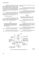
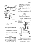
7-76. Governor Cup (Fig. 7-30)
a.
Replace any flyballs that have flat spots or
graves.
b.
Replace cup if race surface is grooved or rough.
The governor cup must be a free spinning fit on camshaft
center pin, but should be replaced if excessively loose or
wobbly.
c.
Check distance the center pin extends from the
camshaft gear. This distance must be 0.781-inch to give
proper travel distance for the cup. If it is less, the engine
may race; if more, the cup will not hold the balls properly.
d.
If
distance is too great, drive or press center pin
in. If it is too small, replace pin; it cannot be removed
without damaging the surface.
e.
If aluminum ball spacer openings are badly worn,
replace ball spacer (camshaft gear must be removed for
this).
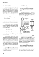
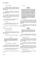
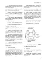
Figure 7-61. Crankshaft Peening.
7-77. Crankshaft
(2)
Bearings.
Replace bearings if clearances are
greater than limits (table 7-2), or if bearings are worn,
grooved, or broken.
(3)
Rear Oil Seal.
Inspect seal (17, fig. 7-27) for
wear or damage which might cause it to leak. Use oil seal
driver 420-0250 (table 5-1 and fig. 7-34) to install new seal.
b.
Rebuild Crankshaft.
If
crankshaft requires
regrinding, metallize and regrind to standards. Special
procedures must be observed when reworking diesel
crankshafts. In addition to regrinding, the crankshaft must
be shot-peened and super-finished. Failure to shot-peen
the crankpin fillets is likely to cause early failure. When
the crankshaft is reground, follow this data and figure 7-61
to shot-peen each crankpin fillet.
(1) Peen with 0.019-inch diameter cast steel shot.
(2) Peen for 30 seconds on each crankpin fillet.
(3) Mask off connecting rod bearing arms.
7-78.
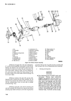
Starter Assembly (Fig. 7-62)
a.
Cleaning and Inspection.
a.
Disassembly.
(1)
Crankshaft.
Clean crankshaft and clear out all
oil passages. Check journals for out-of-round, taper,
grooving, or ridges. Pay particular attention to ridges or
grooves on either side of oil hole areas. Unusual
conditions here often point to previous neglect of oil
changes. If journal dimensions are not within limits or
journals are scored, metallize and regrind crankshaft to
standards (table 7-2).
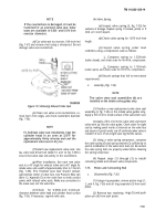
(1) Remove nut (1) and lockwasher (2) from
solenoid (9). Tag and remove lead (3). Disconnect
connector and grommet
(4).
(2)
Remove cotter pin (5) and pin (6) from yoke
(26). Remove screws (7), lockwashers (8), and remove
solenoid switch (9).
7-55
Back to Top

