TM-9-2330-356-14
SEMITRAILER, TANK: 5000 GALLON, BULK HAUL, SELF LOAD/UNLOAD M967 AND M967A1; SEMITRAILER, TANK: 5000 GALLON, FUEL DISPENSING, AUTOMOTIVE M969 AND M969A1; SEMITRAILER, TANK: 5000 GALLON, FUEL DISPENSING, UNDER/OVERWING AIRCRAFT M970 AND M970A1
TECHNICAL MANUAL; OPERATOR’S, UNIT, DIRECT SUPPORT, AND GENERAL SUPPORT MAINTENANCE MANUAL
OCTOBER 1990
TM-9-2330-356-14 - Page 446 of 528
TM 9-2330-356-14
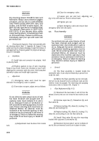
(2) Remove four flat head screws securing
adapter ring (fig. 8-10) 10 caliration section. Remove
adapter ring.
(3) Remove four filister head screws and lift off
calibration section along with the bottom rubber gasket.
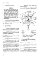
Figure
8-10.
Meter With Register Removed.
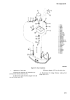
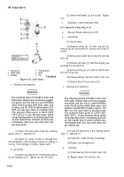
(4)
Remove small snap ring (8, fig. 8-11) from
drive shaft. Remove two screws (9) and insert them into
the two tapped holes in the retainer plate (5). The two
screws will lift the retainer plate from the counter base
plate (1), exposing O-ring (3).
(5) Remove O-ring (3) and replace.
(6) If shims (6) and washers (7) were dislodged
from retainer plate (5), install them into the retainer
plate.
(7) Remove the two screws (9) from the retainer
plate. Position gasket (4) and retainer plate (5) onto
counter baseplate (1), and attach with two screws (9).
(8) Install snap ring (8) onto the shaft.
(9) Position the calibration section (fig. 8-10) and
gasket over the counter base plate (1, fig. 8-11). Fasten the
calibration section with four filister head screws.
(10) Attach adapter ring @g. 8-10) to the
calibration section with four flat head screws.
(11) Position register (fig. 8-9) onto adapter plate
and secure with four capscrews. Install new security wire.
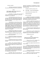
Figure 8-11.
Replacing O-ring in Metez.
Section V. EMERGENCY VALVE VENT AND FLOAT ASSEMBLY
8-8.
Emergency Valve Vent
a.
General. The
emergency valve vent is attached to
the top of the tank near the manhole cover. It is connected
to the emergency valve by an actuating rod (fig. 8-12).
Before the vent can be removed or adjusted, the fuel must
be completely drained from the semitrailer tank and the
interior of the tank must be purged. For draining and
purging instructions, refer to Section XX, Chapter 4.
b.
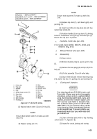
Removal (Fig. 8-12).
(1) Make sure emergency valve is closed.
8-16
Change 1
(2) Remove manhole cover to aid in removal of
the emergency valve vent (para 4-59).
WARNING
Ladder has narrow tread. Use care when climbing.
NOTE
When vent is being removed the connector
and tube will separate from the vent. Hold the
tube while the vent is being removed to keep
it from falling Into tank, then remove the tube.
(3) Remove eight capscrews that fasten the vent
to the top of the tank. Remove the vent and gasket.
* U.S. GOVERNMENT PRINTING OFFICE: 1992 643-016/60119
PIN: 045819-000
Back to Top

