TM-9-2330-356-14
SEMITRAILER, TANK: 5000 GALLON, BULK HAUL, SELF LOAD/UNLOAD M967 AND M967A1; SEMITRAILER, TANK: 5000 GALLON, FUEL DISPENSING, AUTOMOTIVE M969 AND M969A1; SEMITRAILER, TANK: 5000 GALLON, FUEL DISPENSING, UNDER/OVERWING AIRCRAFT M970 AND M970A1
TECHNICAL MANUAL; OPERATOR’S, UNIT, DIRECT SUPPORT, AND GENERAL SUPPORT MAINTENANCE MANUAL
OCTOBER 1990
TM-9-2330-356-14 - Page 450 of 528
TM 9-2330-356-14
Section VI. VALVES
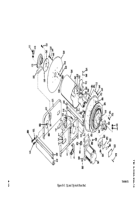
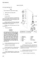
8-10. Gate Valve (Fig. 8-14)
NOTE
It is not necessary to remove valve to repair.
a.
Removal.
Remove valve (para 4-85).
b.
Disassembly.
(1) Secure valve.
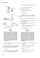
(2) Remove eight capscrews (1), lockwashers (2),
and nuts (3). Lift upper hand wheel assembly from valve
body. Remove gasket (4), and clean mating edges of valve
body and hand wheel assembly.
(3) Loosen packing nut (5) and turn hand wheel
counterclockwise. This will force the spring (6), gland (7),
and packing (8) free of the bonnet (9).
(4) Secure stem (10), and remove nut (11) and
hand wheel (12).
c.
Cleaning
and Inspection.
WARNING
Dry cleaning solvent P-D-680 Is toxic and
flammable. Always wear protective goggles
and gloves, and use only in a well-ventilated
area. Avoid contact with skin, eyes, and
clothes, and DO NOT breathe vapors. DO
NOT use near open flame or excessive heat.
The solvent’s flash point is 100°F-138°F
(38°C-59°C). If you become dizzy while
using cleaning solvent, immediately get fresh
air and medical help. If solvent contacts eyes,
immediately wash your eyes with water and
get medical aid.
(1) Clean metal parts with dry cleaning solvent
(item 11, Appendix E) and dry thoroughly.
(2) Inspect for cracks and pitting.
(3) If disc assembly (13) or its mating surfaces in
valve body are pitted or scored, replace entire valve.
d,
Assembly.
(1) Place packing (8), gland (7), spring (6), and
packing nut (5) on stem (10). Tighten packing nut two full
turns only.
Figure 8-14. Gate Valve,
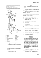
(2) Place gasket (4) in position, and install bonnet
assembly on body. Ensure that disc assembly (13) is at a
right angle to pipe opening. Install eight capscrews (1),
lockwashers (2), and nuts (3).
(3) Place hand wheel (12) and nut (11) on stem.
Turn hand wheel clockwise to seat valve.
e.
Installation.
Install gate valve (para 4-85).
8-20
Back to Top

