TM-9-2350-238-20-1 - Page 721 of 1364
TM 9-2350-238-20-1
1
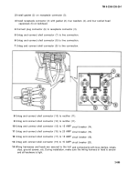
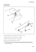
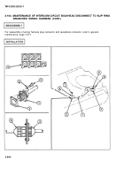
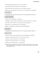
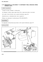
Install intercom circuit bulkhead disconnect to slip ring branched wiring harness (1) in hull.
2
Install new gasket (2) on receptacle connector (3).
3
Install receptacle connector (3) with new gasket (2), washers (4), and four socket head
capscrews (5) on bulkhead.
4
Install ground cable terminal (6) and screw (7) on bulkhead.
5
Connect driver’s control box wiring harness plug connector (8) to receptacle connector (3).
6
Install ground cable terminal (9) and screw (10) on bulkhead.
7
Connect plug connector (11) to slip ring.
8
Wiring harnesses and leads are secured to the hull and components with loop clamps, straps,
clips, ground screws, etc. During installation, make sure the wiring harness or lead is secure
and all hardware is tight.
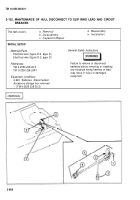
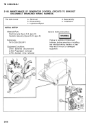
2-105. MAINTENANCE OF HORN TO WARNING RELAY WIRING HARNESS.
This task covers:
a.
Removal
d.
Reassembly
b.
Disassembly
e.
Installation
c.
Inspection/Repair
INITIAL SETUP
Materials/Parts
Electrical wire (figure D-2, appx D)
References
TM 9-2350-238-24P-1
Equipment Conditions
2-640 Batteries disconnected
2-952 Driver’s seat removed
General Safety Instructions
Failure to remove or disconnect batteries before removing or installing any
electrical wiring harness or lead may result in injury or damaged equipment.
2-695
Back to Top

