TM-9-2350-238-20-1 - Page 729 of 1364
TM 9-2350-238-20-1
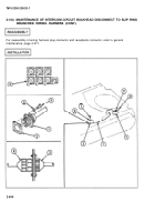
1
Install disconnect to instrument
compartment.
2
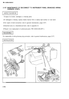
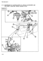
Connect 19 shell connectors to
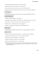
panel branched wiring harness (1) to hull through driver’s
instrument panel at the following points:
a.
Untag and connect eight shell connectors (2) to 24-volt feed.
b.
Untag and connect shell connector (3) to engine and transmission warning light.
c.
Untag and connect shell connector (4) to fuel level indicator.
d.
Untag and connect two shell connectors (5) to high beam panel light.
e.
Untag and connect shell connector (6) to transmission oil temperature indicator.
f.
Untag and connect shell connector (7) to transmission oil pressure indicator.
g.
Untag and connect shell connector (8) to generator charge warning light.
h.
Untag and connect shell connector (9) to engine coolant temperature indicator.
i.
Untag and connect shell connector (10) to engine oil pressure gage.
j.
Untag and connect two shell connectors (11) to master switch panel light.
3
Untag and connect plug connector (12) to engine sending units connector.
4
Wiring harnesses and leads are secured to the hull and components with loop clamps, straps,
clips, ground screws, etc.
During installation, make sure the wiring harness or lead is secure
and all hardware is tight.
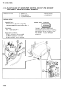
2-108. MAINTENANCE OF DISCONNECT TO FORWARD AIR CLEANER BLOWER
MOTOR ELECTRICAL LEAD.
This task covers:
a.
Removal
b.
Inspection/Repair
c.
Installation
INITIAL SETUP
Materials/Parts
Electrical wire (figure D-2, appx D)
References
TM 9-2350-238-24P-1
Equipment Conditions
2-640 Batteries disconnected
2-952 Driver’s seat removed
General Safety Instructions
Failure to remove or disconnect
batteries before removing or
installing any electrical wiring
harness or lead may result in
injury or damaged equipment.
2-703
Back to Top

