TM-9-2350-238-34-2 - Page 42 of 327
TM 9-2350-238-34-2
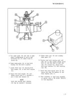
5 Turn cable guide (10) until side of cable
guide is perpendicular to axis of rigid
connecting link (11) within 0.030 in.
(0.076 cm).
6 Clamp cable guide (10) to level wind
housing (12) and hold in position.
7 Loosen three nuts (13) securing level
wind bracket (14) to level wind housing
(12).
8 Adjust level wind bracket (14) until
remote control lever (7) is centered in
slot of level wind bracket (14).
NOTE
Level wind sensing push switches
(15) may be loosened if necessary,
9 Tighten three nuts (13) and unclamp
cable guide (10).
10 Position level wind sensing push swit-
ches (15) so they contact remote control
lever (7), and then back off push swit-
ches (15) one-half turn. Secure level
wind push switches (15) with mounting
nuts (16).
11 Install level wind access cover (3) and
secure with three flat washers (2) and
three machine bolts (1).
12 After installation of level wind assembly
on vehicle, refer to TM 9-2350 -238-20-2
for final adjustment.
2-29
Back to Top

