TM-9-2350-261-20-3 - Page 516 of 932
TM 9-2350-261-20-3
ADJUST RAMP LOCK (M113A2, M901A1, AND M1059 ONLY) — Continued
0556 00
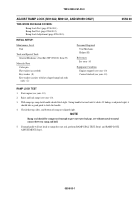
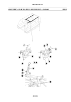
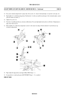
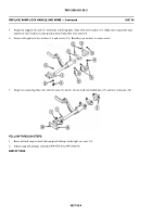
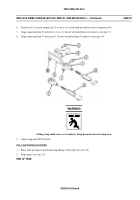
10. For carriers with flat shaped rod (4), place link (10) in clevis (5). Secure with headed pin (11) and new cotter pin (12).
11. Push handle (13) in full forward position. Push bracket (3) to the rear until forward edge of slot in bracket makes contact
with cam surface on latch (1).
12. Tighten two screws (2).
13. The latch (1) should point down as shown in illustration. Put your hand under latch and try to lift latch. If adjustment is
right, latch will not move.
14. Move handle (13) to full released position. Latch (1) will contact rear edge of bolt in bracket (3) and will move up
asshowninillustration.
16. If ramp fails test, check and repeat ADJUSTMENT Steps 1 - 14, as needed.
END OF TASK
0556 00-6
15. Wipe chalk off ramp surface and repeat SEAL TEST Steps 1 - 6.
Back to Top


