TM-9-2350-311-20-2 - Page 337 of 828
TM 9–2350–311–20–2
6–21
6–7
BYPASS VALVE ASSEMBLY
This task covers:
a.
Removal
b.
Installation
INITIAL SETUP
Tools
Artillery and turret mechanic’s tool kit
(SC 5180–95–CL–A12)
Utility pail (item 7, Appx H)
Materials/Parts
Cap and plug set (item 7, Appx D)
Lockwashers (2) (item 67, Appx G)
Lockwashers (4) (item 78, Appx G)
Preformed packings (2) (item 47, Appx G)
Equipment Condition
Discharge hydraulic pressure (para 6–3)
CAB POWER switch to OFF (TM 9–2350–311–10)
Vehicle MASTER switch to OFF (TM 9–2350–311–10)
a.
Removal
1
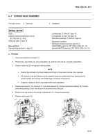
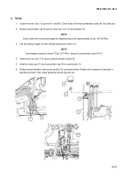
Disconnect electrical connector (1).
2
Remove four cap screws (2), four lockwashers (3), and four hex nuts (4). Discard lockwashers.
3
Remove solenoid (5) from bypass valve assembly.
NOTE
•
Restrict the removal of hydraulic tubes and fittings to those items that are to be replaced.
•
All hydraulic lines and fittings must be capped to prevent contaminants from entering the hy-
draulic system and causing internal damage to hydraulic components.
•
Dispose of hydraulic fluid in accordance with local regulations.
4
Remove two tees (6), four hex nuts (7), two clinch sleeves (8), and two preformed packings (9). Discard
preformed packings. Drain lines at point of disconnect into utility pail.
5
Remove two cap screws (10) and two lockwashers (11). Discard lockwashers.
6
Remove valve body (12).
1
5
2
3
4
7
9
6
8
7
6
10
11
12
Back to Top

