TM-9-2350-311-20-2 - Page 339 of 828
TM 9--2350--311--20--2
Change 4
6--23
6--8
CLUTCH VALVE
This task covers:
a. Removal
b. Installation
INITIAL SETUP
Applicable Configuration
M109A4/M109A5 howitzers
Tools
Artillery and turret mechanic’s tool kit
(CL 5180--95--A12, see SC 9999--01--SKO)
Materials/Parts
Caps and plugs (item 7, Appx D)
Lockwashers (2) (item 68, Appx G)
Lockwashers (3) (item 84, Appx G)
Preformed packings (3) (item 46, Appx G)
Tag, marking (item 36, Appx D)
Equipment Condition
Discharge hydraulic pressure (para 6--3)
CAB POWER switch to OFF (TM 9--2350--311--10)
Vehicle MASTER switch to OFF (TM 9--2350--311--10)
a. Removal
CAUTION
All hydraulic lines and ports must be capped to prevent contaminants from entering the hydraulic
system and causing internal damage to hydraulic components.
1
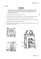
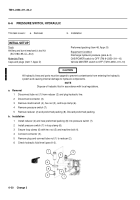
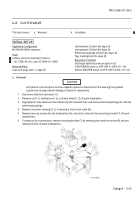
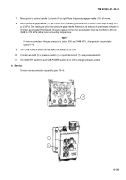
Disconnect electrical connector (1).
2
Remove nut (1.1), lockwasher (1.2), and heat shield (1.3). Discard lockwasher.
3
Tag hydraulic lines. Remove three elbows (2) with attached lines and three preformed packings (3). Discard
preformed packings.
4
Remove insulation sleeving (3.1), if necessary, from clutch valve (6).
5
Remove two cap screws (4), two lockwashers (5), and clutch valve (6) from mounting bracket (7). Discard
lockwashers.
6
If necessary for maintenance, remove mounting bracket (7) by removing two machine screws (8) and two
lockwashers (9). Discard lockwashers.
Back to Top

