TM-9-2350-311-20-2 - Page 341 of 828
TM 9–2350–311–20–2
6–25
6–9
ACCUMULATOR ASSEMBLY (MANUAL PUMP)
This task covers:
a.
Removal
b.
Service
c.
Installation
d.
Testing
INITIAL SETUP
Tools
Artillery and turret mechanic’s tool kit
(SC 5180–95–CL–A12)
Tire pressure gage (item 2, Appx H)
Utility pail (item 7, Appx H)
Equipment Condition
Discharge hydraulic pressure (para 6–3)
a.
Removal
NOTE
Dispose of hydraulic fluid in accordance with local regulations.
1
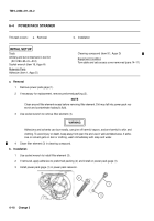
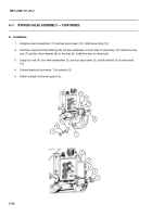
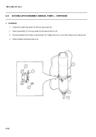
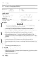
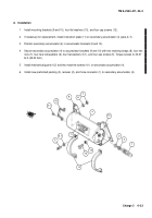
Loosen hex nut (1) and clinch sleeve (2) and disconnect hydraulic line at base of accumulator (3). Drain hy-
draulic fluid from accumulator into a utility pail.
2
Loosen nut (4), open loop clamp (5), and lift out accumulator (3).
3
Inspect loop clamp (5) for damage and serviceability. If defective, perform step 4 to replace loop clamp.
4
Remove two cap screws (6) and loop clamp (5).
b.
Service
Service manual pump accumulator assembly (para 19–3).
3
4
1
2
5
6
Back to Top

