TM-9-2350-311-20-2 - Page 338 of 828
TM 9–2350–311–20–2
6–22
6–7
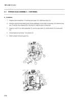
BYPASS VALVE ASSEMBLY — CONTINUED
b.
Installation
1
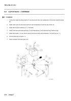
Using two new lockwashers (11) and two cap screws (10), install valve body (12).
2
Insert two new preformed packings (9) into tee receptacles on each side of valve body (12). Install four hex
nuts (7) and two clinch sleeves (8) on two tees (6). Install two tees on valve body.
3
Using four nuts (4), four new lockwashers (3), and four cap screws (2), install solenoid (5) on valve body
(12).
4
Connect electrical connector (1) to solenoid (5).
5
Check hydraulic fluid level (para 6–2).
1
5
2
3
4
7
9
6
8
7
6
10
11
12
Back to Top

