TM-9-2350-311-34-2 - Page 272 of 552
TM
9-2350-311-34-2
6-1
POWER PACK ASSEMBLY - CONTINUED
d. Assembly - Continued
12
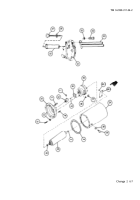
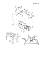
Secure tube assembly (23) to cover assembly (21) with three new lockwashers (30) and three cap screws
(29).
13
14
15
Insert fluid filter element (22) and screw in until seated.
Insert fluid level gage (27) and new preformed packing (28).
Install shim(s) (26) saved during disassembly. Apply 60-100 psi (414-690 kPa) to filter assembly/body as-
sembly (45) and shim as required to obtain a clearance of 0.010 to 0.020 inch (0.25 to 0.5 mm). Measure
distances A and B. The shim thickness = A - B - 0.0156 inch.
16
Install new gasket (25).
One of eight machine bolts is used to secure sight gage to power pack. Do not tighten at this time.
17
Secure cover assembly (21) to power pack reservoir (24) with eight new lockwashers (6) and eight machine
bolts (5).
18
19
Position flexible insert (17) in upper shaft coupling half (42).
Install setscrew (18) in lower shaft coupling half (19). Install woodruff key (20) and lower shaft coupling half
in direct current motor (16) shaft.
20
21
Adjust upper shaft coupling half (42) and lower shaft coupling half (19) to obtain 0.030 inch (0.8 mm) clear-
ance between faces.
Secure direct current motor (16) to power pack reservoir (24) with two of four new lockwashers (11) and two
of four cap screws (10). Torque cap screws to 20-25 lb-ft (27-34 N•m).
NOTE
6-10
Back to Top

