TM-9-2350-311-34-2 - Page 264 of 552
TM 9-2350-311-34-2
6-1
POWER PACK ASSEMBLY
This task covers:
a. Removal
c. Inspection and Repair
e. Installation
b. Disassembly
d. Assembly
INITIAL SETUP
Tools
Artillery and turret mechanic ’s tool kit
(SC 5180-95-CL-A12)
Artillery field maintenance tool kit
(SC 4933-95-CL-A06)
Sling assembly, lifting (item 18, Appx F)
Socket wrench, special (item 23, Appx F)
Materials/Parts
Cotter pins (item 45, Appx E)
Gasket (item 128, Appx E)
Hydraulic fluid (item 22, Appx B)
Lockwashers (8) (item 83, Appx E)
Lockwashers (6) (item 84, Appx E)
Lo&washers (2) (item 95, Appx E)
Lockwashers (4) (item 97, Appx E)
Lo&washers (3) (item 158, Appx E)
Lubricating oil (item 23, Appx B)
Preformed packing (item 53, Appx E)
Preformed packing (item 56, Appx E)
Preformed packing (item 57, Appx E)
Preformed packing (item 59, Appx E)
Preformed packing (item 171, Appx E)
Self-locking nut (item 40, Appx E)
Spring pin (item 12, Appx E)
Personnel Required
2
Discharge hydraulic pressure (TM 9-2350-311-20-2)
Equipment Condition
Drain hydraulic fluid (TM 9-2350-311-20-2)
Lines and fittings from power pack to pressure switch
and gages disconnected (TM 9-2350-311-20-2)
Lines and fittings from cab to power pack disconnected
(TM 9-2350-311-20-2)
Lines and fittings from hydraulic filters disconnected
(Ml 09A4/M109A5) (TM 9-2350-311-20-2)
Lines and fittings from hygroscopic breather discon-
nected (M109A4/M109A5) (TM 9-2350-311-20-2)
Cab access cover removed (TM 9-2350-311-20-2)
a. Removal
1
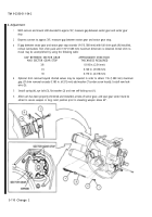
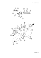
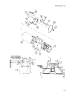
Remove two cap screws (1) from power pack support (2) to disconnect pressure gage (3) and bottom of
sight gage (4).
2
Remove one machine bolt (5) and one lo&washer (6) securing sight gage (4) to top of power pack assem-
bly (7) and remove sight gage.
3
Install lockwasher (6) and machine bolt (5) in top of power pack assembly (7).
4
Remove self-locking nut (8) from hose clamp (9). Discard self-locking nut.
5
Remove two cap screws (10) and two lockwashers (11) from base of power pack assembly (7). Discard
lockwashers.
6
Position lifting sling assembly (12) over power pack assembly (7) and secure with two cap screws (10).
6-2 Change 2
Back to Top

