TM-9-2350-311-34-2 - Page 256 of 552
TM 9-2350-311-34-2
5-15 REPLENISHER ACCUMULATOR ASSEMBLY
This task covers:
a. Disassembly
b. Inspection
c. Assembly
INITIAL SETUP
Tools
Self-locking nut (item 28, Appx E)
Artillery and turret mechanic ’s tool kit
(SC 5180-95-CL-A12)
Personnel Required
2
Materials/Parts
Hydraulic fluid (item 22, Appx B)
Preformed packing (item 58, Appx E)
a. Disassembly
Equipment Condition
Replenisher accumulator assembly removed
(TM 9-2350-311-20-2)
1
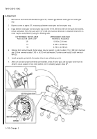
Clamp accumulator (1) in a vise with padding to protect shell.
2
Remove round nut (2), using spanner wrench.
3
Remove shouldered washer (3).
4
Push regulating valve assembly (4) into accumulator shell (5) with palm of hand.
NOTE
Retaining ring is split and is bonded into rubber. It must be folded to remove from accumulator shell.
5
Lift preformed packing (6), ring spacer (7), and retaining ring (8) out of accumulator shell (5). Discard per-
formed packing.
6
Remove regulating valve assembly (4) from accumulator shell (5).
7
Remove self-locking nut (9), valve piston (10), helical compression spring (11), and fluid valve stem (12)
from port (13). Discard self-locking nut.
NOTE
If cap MS 20813-1 is present on gas valve, retain for cap valve 9399173.
8
Remove cap assembly (14), pneumatic valve core (15), and hex nut (16).
9
Grasp accumulator bag (17) and gas valve (18) and compress to remove all gas. Withdraw from accumula-
tor shell (5).
b. Inspection
1
Inflate accumulator bag (17) and submerge accumulator bag, gas valve (18), and pneumatic valve core (15)
in water. Replace accumulator bag if there are signs of leakage or if gas valve is cracked or loose.
2
Inspect accumulator shell (5). Replace accumulator if cracked or distorted.
3
Inspect fluid valve stem (12). Replace if damaged.
5-110.2 Change 2
Back to Top


