TM-9-2350-311-34-2 - Page 257 of 552
TM 9-2350-311-34-2
c. Assembly
1
2
3
4
5
6
7
8
9
10
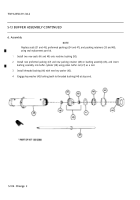
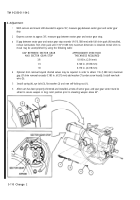
Assemble fluid valve stem (12), helical compression spring (11), valve piston (10), and new self-locking nut
(9) into port (13).
Pour a small amount of hydraulic fluid into accumulator shell (5) as a cushioning fluid (heavy coating on inte-
rior of accumulator shell).
Deflate accumulator bag (17) and gas valve (18). Install pneumatic valve core (15).
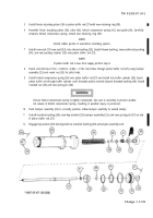
Fold accumulator bag (17) and gas valve (18) to enter accumulator shell (5) with minimum friction. Guide
gas valve stem with hand through hole in wider end of accumulator shell.
Install hex nut (16) securely.
Install regulating valve assembly (4) into accumulator shell (5).
Place retaining ring (8) on regulating valve assembly (4) with small shoulder toward shell mount and fold to
insert.
Place ring spacer (7) on regulating valve assembly (4) and install new preformed packing (6).
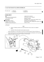
Withdraw regulating valve assembly (4) threaded portion through shell mouth. Pull until solidly seated and
preformed packing (6) is squeezed.
Install shouldered washer (3) on regulating valve assembly (4), then install round nut (2). Tighten round nut
securely.
5-111
Back to Top


