TM-9-2350-311-34-2 - Page 260 of 552
TM 9-2350-311-34-2
5-17
VARIABLE RECOIL ASSEMBLY AND BUFFER AND REPLENISHER MANIFOLD, HOSES,
LINES, AND FITTINGS
This task covers:
a. Removal
b. Installation
INITIAL SETUP
Tools
Artillery and turret mechanic’s tool kit
(SC 5180-95-CL-A12)
Materials/Parts
Cap and plug set (item 10, Appx B)
LockWire (item 36, Appx E)
Packing retainer (item 61, Appx E)
Plastic bag (item 6, Appx B)
Preformed packing (item 67, Appx E)
Preformed packing (item 99, Appx E)
Preformed packings (3) (item 65, Appx E)
Self-locking nut (item 98, Appx E)
References
TM 9-2350-311-20-2
Equipment Condition
Replenisher assembly pressure discharged (para 5-14)
Discharge hydraulic pressure (TM 9-2350-311-20-2)
a. Removal
Eye protection will be worn when performing maintenance procedures on all hydraulic components
to avoid injury to personnel.
All hydraulic lines and ports must be capped to prevent contaminants from entering the hydrau-
lic system and causing internal damage to hydraulic components.
All serviceable components must be placed in plastic bags to prevent contamination of hydrau-
lic system during installation.
NOTE
All hydraulic lines and components must be tagged before removal for identification during in-
stallation.
The removal of hydraulic tubes and fittings must be restricted to those items that are to be re-
placed. Therefore, the legends in this chapter are for identification only.
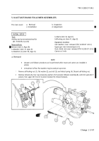
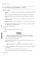
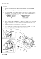
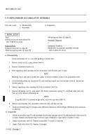
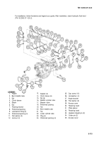
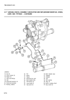
For removal, follow illustration and legend as a guide, Discard all lockwire, preformed packings, self-locking
nuts, and packing retainers.
5-114
Back to Top


