TM-9-2350-311-34-2 - Page 268 of 552
TM 9-2350-311-34-2
6-1
POWER PACK ASSEMBLY - CONTINUED
b. Disassembly - Continued
9
10
11
12
13
14
15
16
17
18
19
20
21
22
23
24
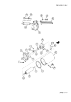
Withdraw fluid level gage (27) and preformed packing (28). Discard preformed packing.
Unscrew and remove fluid filter element (22) using special socket wrench.
Remove three cap screws (29) and three lockwashers (30) from cover assembly (21). Discard lockwashers.
Remove tube assembly (23).
Remove four cap screws (31) and four lockwashers (32) securing mount assembly (33) to power pack
reservoir (24). Tap mount assembly lightly with soft face hand hammer to separate. Discard lo&washers.
Remove and discard preformed packing (34).
NOTE
If you have received a new power pack reservoir, perform step 15. If not, skip to step 16.
Remove plug (35) and preformed packing (36) from power pack reservoir (24). Discard preformed packing
and plug.
Remove two hex nuts (37) and two lockwashers (38) securing rotary pump (39) to mount assembly (33).
Remove rotary pump. Discard lockwashers.
Remove and discard preformed packing (40).
Remove setscrew (41) from upper shaft coupling half (42).
Remove upper shaft coupling half (42) and machine key (43) from rotary pump (39).
Remove preformed packing (44) from filter assembly/body assembly (45) and discard.
Separate filter assembly/body assembly (45) from rotary pump (39).
Remove preformed packing (46) from filter assembly/body assembly (45) and discard.
If necessary for replacement, remove two plain studs (47) and spring pin (48). Discard spring pin.
If necessary for replacement, remove four drive screws (48.1) and identification plate (48.2) from power
pack reservoir (24).
6-6 Change 2
Back to Top

